High-heat conductivity coefficient graphite heat-radiation adhesive tape

A technology of high thermal conductivity and thermally conductive adhesive, applied in the direction of adhesives, film/sheet adhesives, non-metallic elements, etc., can solve the problems of increasing the thermal conductivity of graphite heat sinks, limiting the application range of graphite heat sinks, and limited functions. Achieve the effects of reducing the probability of graphite cracking, facilitating graphite cutting, and improving performance and life

Active Publication Date: 2013-04-24
斯迪克新型材料(江苏)有限公司
View PDF9 Cites 65 Cited by
  • Summary
  • Abstract
  • Description
  • Claims
  • Application Information

AI Technical Summary

Problems solved by technology

[0005] Although these methods can partially improve the thermal conductivity of graphite materials, the effect is limited. The thermal conductivity is generally lower than 600, while the thermal conductivity of a graphite single crystal surface can reach 2200. It can be seen that the thermal conductivity of graphite ...

Method used


Image

  • High-heat conductivity coefficient graphite heat-radiation adhesive tape
  • High-heat conductivity coefficient graphite heat-radiation adhesive tape
  • High-heat conductivity coefficient graphite heat-radiation adhesive tape

Examples


Embodiment 1

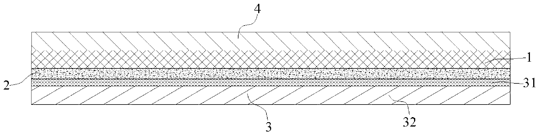
[0032] Embodiment 1: A graphite thermal tape with high thermal conductivity comprises a graphite layer 1, the upper surface of the graphite layer 1 is covered with a metal layer 4, the lower surface of the graphite layer 1 is coated with a thermally conductive adhesive layer 2, and a The molded film 3 is attached to the other surface of the thermally conductive adhesive layer 2; the graphite layer 4 is obtained through the following process, which process includes the following steps:

[0033] Step 1. Add triethylamine to the polyamic acid solution, stir well and apply it on the organic substrate layer;

[0034] Step 2, under the protection of nitrogen, keep the temperature at 80°C for 0.95 hours;

[0035] Step 3, place in an oven in a vacuum environment, keep the temperature at 100°C for 1.05 hours, then raise the temperature to 300°C, keep the temperature at 0.9 hours and then cool naturally, so as to obtain a polyimide film;

[0036] Step 4. Under the protection of inert g...

Embodiment 2

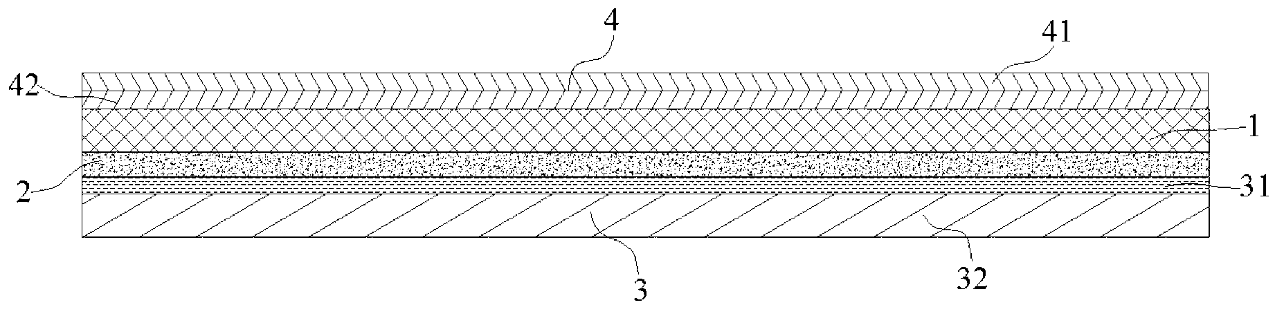
[0041] Embodiment 2: a graphite thermal tape with high thermal conductivity, comprising a graphite layer 1, the upper surface of the graphite layer 1 is covered with a metal layer 4, the lower surface of the graphite layer 1 is coated with a thermally conductive adhesive layer 2, a The molded film 3 is pasted on the other surface of the thermally conductive adhesive layer 2; the metal layer 4 is composed of an aluminum layer 41 and a copper layer 42 laminated, and the copper layer 42 is located between the aluminum layer 41 and the graphite layer 1;

[0042] The graphite layer 4 is obtained by the following process, which comprises the following steps:

[0043] Step 1. Add ethylene glycol to the polyamic acid solution, stir well and apply it on the glass substrate layer;

[0044] Step 2, under the protection of nitrogen, keep the temperature at 80°C for 1 hour;

[0045] Step 3, place in an oven in a vacuum environment, keep the temperature at 100°C for 1 hour, then raise the te...


PUM


Abstract

The invention discloses a high-heat conductivity coefficient graphite heat-radiation adhesive tape. The high-heat conductivity coefficient graphite heat-radiation adhesive tape comprises a graphite layer. A metal layer is coated on an upper surface of the graphite layer. A heat-radiation adhesive layer is coated on a lower surface of the graphite layer. The graphite layer is prepared by adding ethylene glycol or triethylamine into a polyamide acid solution, heating to a temperature of 300 DEG C to obtain a polyimide film, heating the polyimide film to a temperature of 250 DEG C, heating to a temperature of 1200 DEG C to obtain a pre-sintered carbonized film, rolling the pre-sintered carbonized film by a roller mill, heating to a temperature of 2400 DEG C, heating to a temperature of 2900 DEG C to obtain a mainly sintered graphite film, and rolling the mainly sintered graphite film. The high-heat conductivity coefficient graphite heat-radiation adhesive tape has high heat conduction performances in vertical and horizontal directions, avoids adhesive tape local overheating and realizes uniformity of adhesive tape heat conduction performances.

Description

technical field [0001] The invention relates to a graphite heat dissipation adhesive tape with high thermal conductivity, which belongs to the technical field of adhesive tapes. Background technique [0002] With the rapid development of modern microelectronics technology, electronic devices (such as laptops, mobile phones, tablet computers, etc.) are increasingly becoming ultra-thin and lightweight. This structure makes the internal power density of electronic devices significantly increased, and the heat generated during operation is not easy to discharge , Easy to accumulate rapidly and form high temperature. On the other hand, high temperatures can reduce the performance, reliability and lifespan of electronic equipment. Therefore, the current electronics industry has put forward higher and higher requirements for heat dissipation materials as the core components of thermal control systems, and there is an urgent need for a highly efficient heat-conducting, lightweight ...

Claims


Application Information

Patent Timeline
IPC IPC(8): C09J7/02C01B31/04C01B32/205
Inventor 金闯杨晓明李炜罡
Owner 斯迪克新型材料(江苏)有限公司
Why Eureka
Try Eureka