Dust cleaning system applicable to heat recovery boiler with complex heating surface

A waste heat boiler and heating surface technology, which is used in the removal of solid residues, lighting and heating equipment, combustion products treatment, etc., can solve problems such as difficulty in using waste heat boilers, unsuitable recovery of granular materials, and poor airtightness.

Inactive Publication Date: 2013-04-24
BEIJING CENTURY BENEFITS
View PDF9 Cites 7 Cited by
  • Summary
  • Abstract
  • Description
  • Claims
  • Application Information

AI Technical Summary

Problems solved by technology

A method and device for removing cohesive ash deposits in boilers announced by China (patent publication number CN100404956C) proposes a method that uses 0.5-10mm river sand, quartz sand and alumina particles as boiler tail flue and tube type. It is a device for removing ash particles on the heat exchange surface of the waste heat boiler, which acts on the heat exchange surface with the flue gas to remove ash deposits. This ash removal technology is that when the ash is highly cohesive, it is easy to form agglomerates with the granular materials and is not easy to separate At this time, the granular material is not suitable for recycling, especially for systems that need to recover dust; on the other hand, compared with fine-grained steel shots, the granular material is more likely to accumulate between the fins/fins/annular fins , affecting the heat transfer effect
The published invention patent (patent authorization number CN202066040U) proposes a pill cleaning system that uses horizontal and vertical screw conveyors to transport pills, and is equipped with a pill meter...

Method used


Image

  • Dust cleaning system applicable to heat recovery boiler with complex heating surface
  • Dust cleaning system applicable to heat recovery boiler with complex heating surface
  • Dust cleaning system applicable to heat recovery boiler with complex heating surface

Examples


Embodiment

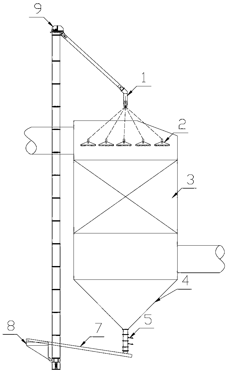
[0023] like Figure 1 to Figure 5 As shown, the present invention relates to a ash cleaning method or system suitable for a waste heat boiler with a complex heating surface, and the purpose is to develop a waste heat boiler with a complex heating surface such as fins / fins / annular fin tubes that can adapt to 24-hour operation. The ash cleaning system, through reasonable and efficient shot distribution device, shot collection system, screening system, and transportation and lifting system, can obtain a heating surface cleaning system or device with more stable and reliable operation, lower investment and better cleaning effect, It is planned to replace the conventional ash cleaning device in some flue gas waste heat recovery occasions.

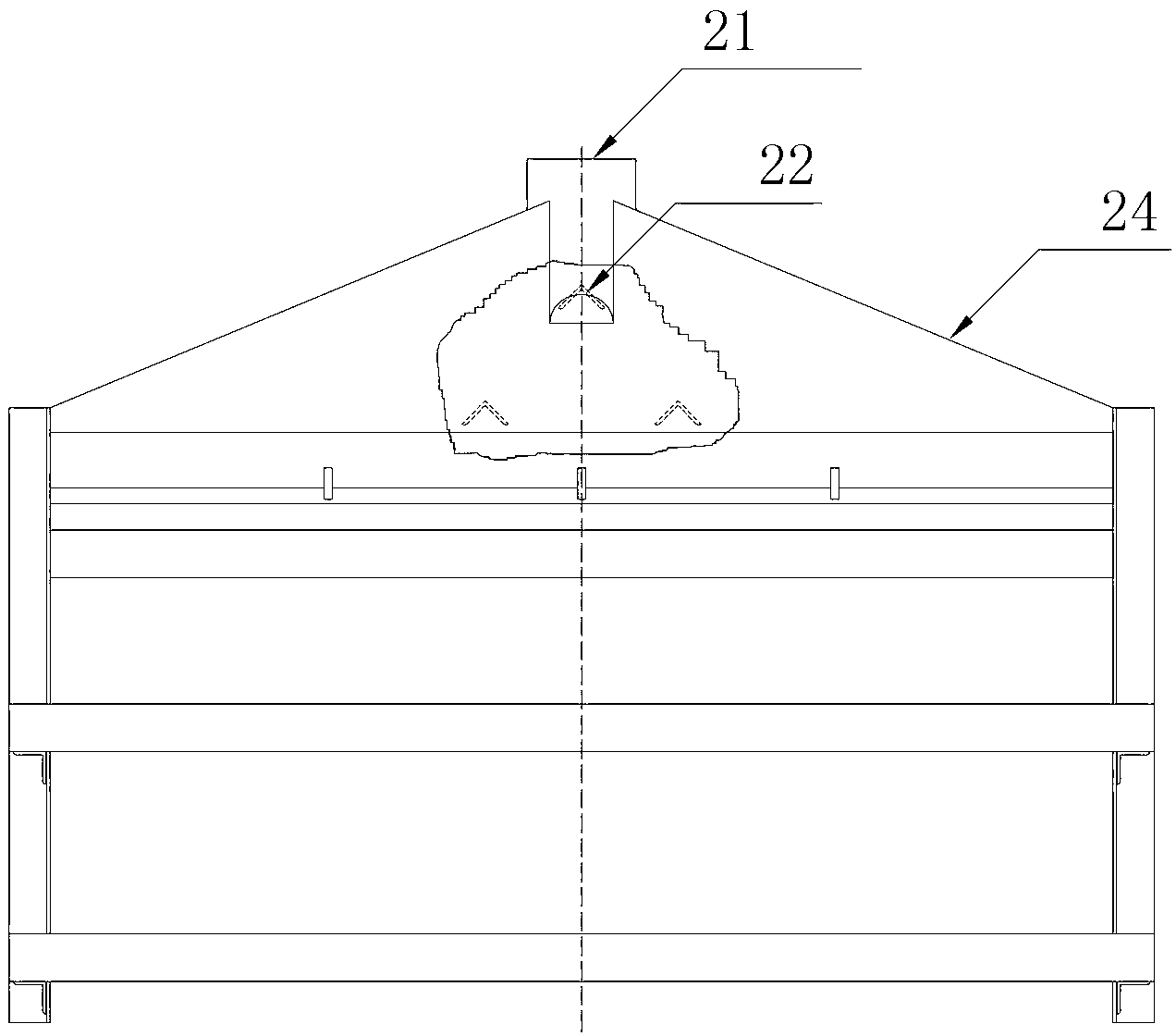
[0024] The present invention is a waste heat boiler cleaning method system suitable for complex heating surfaces, including a pelletizing device 1, a pellet distributor 2, a waste heat boiler 3, a pellet collecting hopper 4, a flap valve 5, and ...


PUM

PropertyMeasurementUnit
Particle sizeaaaaaaaaaa

Abstract

The invention discloses a dust cleaning system applicable to a heat recovery boiler with a complex heating surface. The dust cleaning system comprises a lifter, a shot separating device, a shot distributer, a sealed flap valve, a separating device, a shot storing bin and a horizontal shot conveying device. The shot distributer is a slot type shot distributor, the slot type shot distributor is good in shot distributing effect, can guarantee full coverage on a first heat exchange tube layer, structurally effectively buffer falling speed of steel shots, and reduce impact of the steel shots to the heat exchange tubes and anti-wear strips; the steel shots in grain size of 2-4mm are utilized, compared with a conventional shot-falling dust cleaning system, the dust cleaning system is more applicable to dust cleaning of the heat recovery boiler utilizing a complex heating surface like a radiator fin/a fin/an annular fin tube to strengthen heat exchange, dispersity and distributing compactness of the shots on the heating surface are easier to guaranteed, and dust cleaning effect is good; and impact to the surfaces of the heat exchange tubes from the small-grain-size steel shots is lower, and service life of equipment is prolonged. The dust cleaning system applicable to the heat recovery boiler with the complex heating surface is capable of immediately effectively cleaning dust on the surface of the heating surfaced, is stable in running, low in investment and maintenance cost, and can maintain high efficient heat exchange of the complex heating surface.

Description

technical field [0001] The invention relates to a waste heat boiler ash cleaning method or system in the fields of waste heat recovery and power generation, in particular to a waste heat boiler that utilizes complex heating surfaces such as fins, fins, annular fins and other complex heating surfaces to strengthen heat exchange for flue gas waste heat recovery and power generation. Ash cleaning system to ensure the heat transfer efficiency of the heating surface. Background technique [0002] The use of fins, fins or annular fins to strengthen the heat exchange means to enhance the airflow heat exchange outside the heat exchange tube is a form of enhanced heat exchange that is often used in high-efficiency heat exchange tubes, which can greatly enhance the entire heat transfer process. , saves the metal consumption of heat exchange tubes, saves floor space, improves the economy of waste heat recovery equipment, and has good application prospects in industrial energy saving an...

Claims


Application Information

Patent Timeline
IPC IPC(8): F23J3/02
Inventor 涂爱民陈恩鉴阳德志程珩
Owner BEIJING CENTURY BENEFITS
Why Eureka
Try Eureka