Chromatic dispersion shear image surface interference hyper spectrum imaging device and method

An imaging device and hyperspectral technology, which is applied in the field of optical target detection, can solve the problems of not being able to select materials, affecting the imaging quality of the instrument, etc., and achieve the effects of simple and practical method, high target resolution, and improved spectral resolution.

Active Publication Date: 2013-04-24
NANJING UNIV OF SCI & TECH
9 Cites 21 Cited by

AI-Extracted Technical Summary

Problems solved by technology

However, there are several problems in this method for imaging detection: (1) Limited by the dispersion characteristics of the prism, in the obtained spectral information, the spectral resolution at the long-wavelength band is much smaller than that at the short-wavelength band, so It is selective to the detection band; (2) This method can only improve the spectral resolution by changing the material and thickness of ...

Abstract

The invention provides a chromatic dispersion shear image surface interference hyper spectrum imaging device and a method. The chromatic dispersion shear image surface interference hyper spectrum imaging device comprises a front-placed optical system, an Sagnac chromatic dispersion shear beam splitting system, an imaging system and a signal processing system, wherein the front-placed optical system, the Sagnac chromatic dispersion shear beam splitting system, the imaging system and the signal processing system are placed in sequence along a light path direction. Incident light from each target point enters the front-placed optical system, a target view field is confirmed, stray light is eliminated, and collimated light beams are formed. The collimated light beams enter the Sagnac chromatic dispersion shear beam splitting system, are sheared into two transversely and form two beams of light with the shearing distance changing with the wave number. The two beams of light enter the imaging system, and a target image carrying with interference information is obtained on a detector target surface at an imaging objective lens back focal plane position. A detection target is pushed and swept so as to obtain the interference information of each target point under different optical path differences. The signal processing system conducts fourier transformation to the interference information so as to obtain spectral information of each target point and two-dimensional image information of each spectrum segment. The chromatic dispersion shear image surface interference hyper spectrum imaging method has the advantages of a hyper-spectrum spectral resolution ratio, a high light quantity, a high target resolution ratio and the like.

Application Domain

Technology Topic

Optical pathSpectral imaging +11

Image

  • Chromatic dispersion shear image surface interference hyper spectrum imaging device and method

Examples

  • Experimental program(1)

Example Embodiment

[0020] The present invention will be further described below in conjunction with the drawings and specific embodiments.
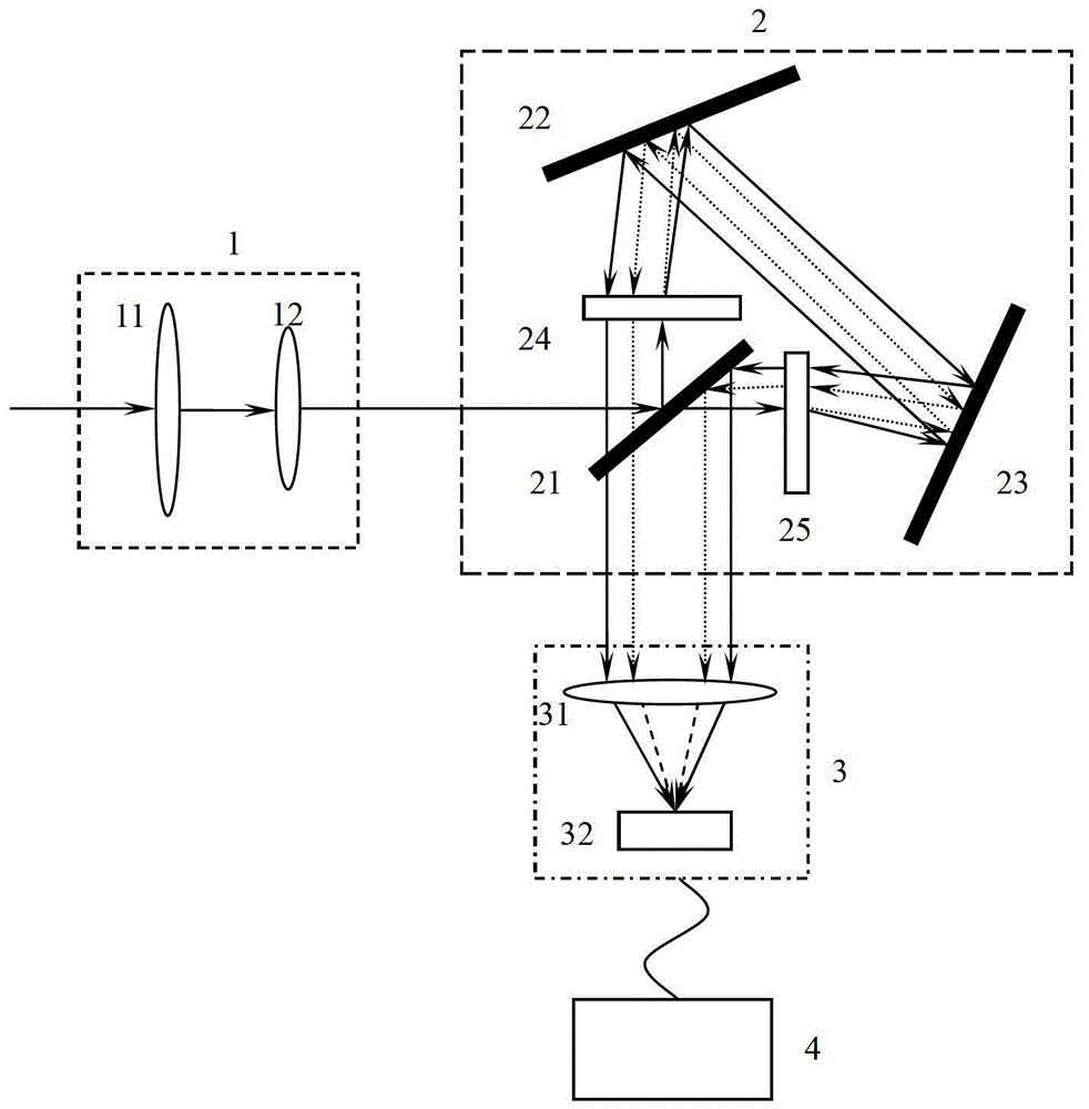
[0021] Combine figure 1 , The dispersion-shearing image plane interference hyperspectral imaging device of the present invention includes a front optical system 1, a Sagnac dispersion-shearing beam splitting system 2, an imaging system 3, and a signal processing system 4 sequentially placed along the optical path; The system 1 includes a front imaging objective lens 11 and a collimating objective lens 12 arranged in sequence along the optical path. The image plane of the front imaging objective lens 11 coincides with the front focal plane of the collimating objective lens 12; the Sagnac dispersion shearing beam splitting system 2 includes common light The beam splitter 21, the first diffraction grating 24, the first high-reflection mirror 22, the second high-reflection mirror 23, and the second diffraction grating 25 are arranged clockwise in the axis, in which the first diffraction grating 24 and the second diffraction grating 25 have specifications The same, and placed along the optical axis perpendicular to the Sagnac dispersion shearing beam splitting system 2; the imaging system 3 includes an imaging objective lens 31 and a detector 32 arranged in order along the optical path direction, wherein the target surface of the detector 32 is located on the imaging objective lens 31 On the back focal plane; the signal processing system 4 is connected to the detector 32; all the optical elements are coaxially and equally high relative to the substrate, that is, relative to the optical platform or the instrument base.
[0022] In the dispersion-sheared image plane interference hyperspectral imaging device of the present invention, the optical path of the Sagnac dispersion-shearing beam splitting system 2 is as follows: the collimated beam formed by the front optical system 1 passes through the beam splitter 21 to form the first reflected light and the second One transmitted light and two: the first reflected light first enters the first diffraction grating 24 and is diffracted, and the outgoing beam forms a divergent light. The divergence angle changes with the wave number, and then passes through the first high mirror 22 and the second high mirror 23. It is incident on the second diffraction grating 25. After passing through the second diffraction grating 25, the divergent beam forms a parallel beam, which is incident on the beam splitter 21 to form two second reflected light and second transmitted light. The second reflected light enters the imaging system 3 imaging objective lens 31; the first transmitted light first enters the second diffraction grating 25, diffracts, the outgoing beam forms divergent light, the divergence angle changes with the wave number, and then passes through the second high mirror 23 and the first high mirror 22, When incident on the first diffraction grating 24, the divergent light beam passes through the first diffraction grating 24 to form a parallel beam, which is incident on the beam splitter 21 to form a third reflected light and a third transmitted light. The third transmitted light beam enters the imaging system 3 imaging objective lens 31.
[0023] The imaging method of the dispersive shearing image plane interference hyperspectral imaging device of the present invention has the following steps:
[0024] In the first step, the incident light from each point of the target enters the front optical system 1 to determine the target field of view, eliminate stray light and form a collimated beam;
[0025] In the second step, the formed collimated beam enters the beam splitter 21 of the Sagnac dispersion shearing beam splitting system 2, and is split into two by transverse shearing, forming two beams whose shearing distance varies with the wave number;
[0026] In the third step, the two beams of light cut by the Sagnac dispersion shearing beam splitting system 2 enter the imaging objective lens 31 of the imaging system 3, and the target surface of the detector 32 at the back focal plane of the imaging objective lens 31 is obtained with interference information. Target image; push and scan the target, change the optical path difference range of the two beams of light that have been cut through the imaging objective lens 31 to the detector 32, and generate interference information corresponding to the varying optical path difference range on the target surface of the detector 32 The target image with interference information is converted into an electrical signal and enters the signal processing system 4;
[0027] In the fourth step, the signal processing system 4 extracts the interference data under different optical path differences at each point of the target from the received electrical signal, and performs Fourier transform on the interference data to obtain the restored target image, thereby obtaining the spectrum of each point of the target Information and two-dimensional image information of each spectrum.
[0028] The detection steps of the dispersive shearing image plane interference hyperspectral imaging device of the present invention are:
[0029] (1) The light emitted or reflected by the detection target is imaged on its image surface through the front imaging objective lens 11 to eliminate stray light, and then passes through the collimating objective lens 12 to form a collimated beam, which enters the Sagnac dispersion shearing element as a collimated beam. Beam system 2;
[0030] (2) The collimated light beam formed by the front optical system 1 passes through the beam splitter 21 to form two first reflected light and first transmitted light: the first reflected light first enters the first diffraction grating 24, is diffracted, and the beam is emitted The divergent light is formed, the divergence angle changes with the wave number, and satisfies the grating equation:
[0031] d(sini+sinθ)=m/σ
[0032] In the formula, d is the grating constant, i is the incident angle of the grating, θ is the exit angle, that is, the divergence angle, m is the diffraction order, and σ is the wave number;
[0033] After passing through the first high-reflection mirror 22 and the second high-reflection mirror 23, it is incident on the second diffraction grating 25. After the divergent light beam passes through the second diffraction grating 25, a parallel beam is formed, which is incident on the beam splitter 21 to form a second reflected light. The second reflected light enters the imaging system 3; the first transmitted light first enters the second diffraction grating 25 and is diffracted. The outgoing beam forms a divergent light. The divergence angle changes with the wave number, and then passes through the second The high-reflection mirror 23 and the first high-reflection mirror 22 are incident on the first diffraction grating 24. After the divergent light beam passes through the first diffraction grating 24, a parallel beam is formed, which is incident on the beam splitter 21 to form a third reflected light and a third transmission Two branches of light, of which the third transmitted light beam enters the imaging system 3.
[0034] (3) The shearing amount of the second reflected light and the third transmitted light emitted from the beam splitter 21, that is, the horizontal shearing distance is transformed with the wave number, and then the optical path difference information transformed with the wave number is introduced, and then the light beam is converged by the imaging objective lens 31 Go to the target surface of the detector 32 at the back focal plane of the imaging objective lens 31, and rotate the Sagnac dispersion transverse shear beam splitter 2 through the electronically controlled rotating platform or rotate the entire system to push and sweep the measured target to obtain the target points Target interference images carrying interference information under different optical path differences are converted into electrical signals and enter the signal processing system 4; the signal processing system 4 is a computer equipped with signal processing software;
[0035] (4) The signal processing system 4 extracts the interference data of each object point with different optical path differences, and performs Fourier transform to obtain the super-resolution spectral information of each target point and the two-dimensional image information of each spectral band.
[0036] The front component of the detector of the dispersive shearing image plane interference hyperspectral imaging device of the present invention is an all-optical device, without acousto-optic and electro-optic modulation, and the method is simple and practical; it has the advantages of high target resolution and high flux; and can improve the interference imaging spectrum technology Spectral resolution, to achieve sub-nanometer resolution spectral imaging detection.

PUM

no PUM

Description & Claims & Application Information

We can also present the details of the Description, Claims and Application information to help users get a comprehensive understanding of the technical details of the patent, such as background art, summary of invention, brief description of drawings, description of embodiments, and other original content. On the other hand, users can also determine the specific scope of protection of the technology through the list of claims; as well as understand the changes in the life cycle of the technology with the presentation of the patent timeline. Login to view more.

Similar technology patents

Customized financial transaction pricing

ActiveUS20100114713A1Accurate and efficient calculationSimple methodComplete banking machinesFinanceProduct dataPayment processor
Owner:AMERICAN EXPRESS TRAVEL RELATED SERVICES CO INC

Aluminum-silicon alloy refining agent and preparation thereof

Owner:营口经济技术开发区金达合金铸造有限公司

Classification and recommendation of technical efficacy words

Why Eureka
Try Eureka