Heat or flow management system used for passive type direct methanol fuel cell

A methanol fuel cell, passive technology, applied to fuel cell parts, fuel cells, fuel cell additives, etc., can solve the problems of two-phase mass transfer at the two poles of the battery, limit the performance of DMFC, and low utilization of methanol, etc., to improve Effects of energy utilization, increase in mass transfer resistance and heat transfer rate, and increase in fuel utilization

Active Publication Date: 2015-04-22
SOUTH CHINA UNIV OF TECH +1
View PDF9 Cites 0 Cited by
  • Summary
  • Abstract
  • Description
  • Claims
  • Application Information

AI Technical Summary

Problems solved by technology

Although my country has achieved certain research results in DMFC research and development at the present stage, they all use liquid methanol solution as raw material, which inevitably encounters the following problems: (1) Methanol penetration is serious, power density is low, methanol utilization (2) The concentration of methanol is low, and the methanol reaching the anode is diluted; (3) The reaction temperature is low (≤90°C), and the battery activity is low; (4) Two-phase mass transfer is hindered at both electrodes of the battery
The above factors work together to greatly limit the performance of DMFC, making people have to continue to explore the use of steam supply to provide fuel for DMFC

Method used


Image

  • Heat or flow management system used for passive type direct methanol fuel cell
  • Heat or flow management system used for passive type direct methanol fuel cell
  • Heat or flow management system used for passive type direct methanol fuel cell

Examples


Embodiment

[0041] In order to further understand the present invention, the present invention will be further described below in conjunction with the accompanying drawings and examples, but it should be noted that the protection scope of the present invention is not limited to the scope expressed in the examples.

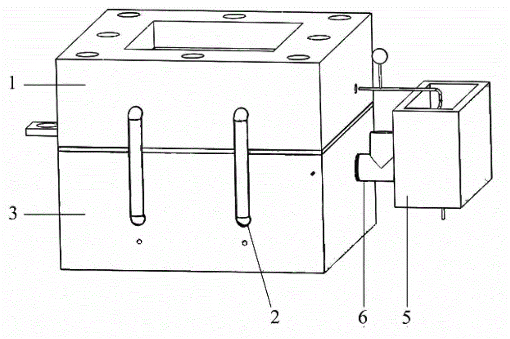
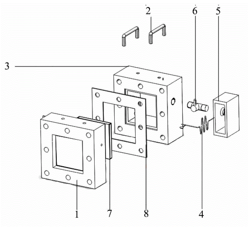
[0042] Heat / flow management system for passive direct methanol fuel cells, including evaporator 3, temperature control system, reactant recovery device, heat balance device, insulation layer; reactant recovery device includes serpentine pipeline 4 and methanol cooling box 5 One end of the serpentine pipeline 4 is connected to the reactant outlet of the battery reactant 1, and the other end passes through the through hole 20 at the bottom of the methanol cooling box 5, and the middle part is placed in the methanol chamber 21 of the methanol cooling box 5; the methanol cooling box 5 Placed in a room temperature environment, liquid methanol is stored inside, and the lower part of ...


PUM

PropertyMeasurementUnit
pore sizeaaaaaaaaaa
diameteraaaaaaaaaa
thicknessaaaaaaaaaa

Abstract

The invention discloses a heat or flow management system used for a passive type direct methanol fuel cell. The heat or flow management system used for the passive type direct methanol fuel cell comprises an evaporator, a temperature control system, a reactant recovery device and a heat balance device. The reactant recovery device comprises a snake-shaped pipeline and a methanol cooling box. One end of the snake-shaped pipeline is connected with a reactant outlet of a cell reaction body. The other end of the snake-shaped pipeline penetrates through the lower portion of the methanol cooling box. The middle portion of the snake-shaped pipeline is arranged in the methanol cooling box. The methanol cooling box is arranged in room temperature environment. Liquid methanol is stored on the interior of the methanol cooling box. The lower portion of a box body is communicated with the evaporator through a valve. The heat balance device is composed of heat pipes in an evenly arranged and combined mode. According to the heat or flow management system used for the passive type direct methanol fuel cell, fuel for a cell reaction is provided through a steam form, the problem of penetration of methanol is effectively solved, an alcohol resistant property of the passive type direct methanol fuel cell is improved, working can be achieved under a condition with high methanol concentration, a fuel using rate is improved, speed of the cell reaction is improved due to improvement of positive electrode reactant temperature and pressure, and therefore a discharging rate is improved.

Description

technical field [0001] The invention relates to the technical field of fuel cells, in particular to a heat / flow management system for passive direct methanol fuel cells. Background technique [0002] Direct methanol fuel cell (Direct Methanol Fuel Cell, hereinafter referred to as DMFC) is a fuel cell that directly uses methanol aqueous solution as fuel and oxygen or air as oxidant. [0003] The half-cell and total reactions of DMFC can be expressed as follows: [0004] The anode reaction is CH 3 OH+H 2 O→6H + +6e - +CO 2 [0005] The cathode reaction is 3 / 2O 2 +6H + +6e - →3H 2 o [0006] The total reaction of the battery is CH 3 OH+3 / 2O 2 →2H 2 O+CO 2 [0007] Due to its high energy density, readily available fuel, convenient use, simple equipment, and environmental protection, DMFC is considered by the industry to be a type of fuel cell with the most potential to be marketed first. Although my country has achieved certain research results in DMFC research ...

Claims


Application Information

Patent Timeline
Patent Type & Authority Patents(China)
IPC IPC(8): H01M8/04H01M8/02H01M8/06H01M8/1011
CPCY02E60/50
Inventor 袁伟张兆春汤勇黄子洋
Owner SOUTH CHINA UNIV OF TECH
Why Eureka
Try Eureka