Multi-stage plasma carbon material cracking reactor, and method for producing acetylene by using carbon material

A technology of plasma and carbonaceous materials, applied in the field of ions, can solve the problems of single-stage reactor height that cannot be lengthened at will, limited conversion, energy waste, temperature distribution, etc.

Active Publication Date: 2013-05-08
CHNA ENERGY INVESTMENT CORP LTD +1
View PDF13 Cites 13 Cited by
  • Summary
  • Abstract
  • Description
  • Claims
  • Application Information

AI Technical Summary

Problems solved by technology

For example, when the reaction time of carbonaceous material powder needs to be increased or optimized according to the reaction temperature required by the maximum yield of cracking products such as acetylene, the height of the single-stage reactor cannot be arbitrarily lengthened
The temperature of the hot gas stream drops rapidly along the longitudinal direction of the single-stage reactor, resulting in that the reaction gas stream must be quenched within a short travel distance in order to maximize the yield of cracked products, and thus makes the conversion of carbonaceous materials into cracked products very difficult. limited
At the same time, as mentioned before, the serious waste of energy and the excessively high temperature distribution near the inner wall of the reactor are also serious technical problems that cannot be ignored.

Method used


Image

  • Multi-stage plasma carbon material cracking reactor, and method for producing acetylene by using carbon material
  • Multi-stage plasma carbon material cracking reactor, and method for producing acetylene by using carbon material
  • Multi-stage plasma carbon material cracking reactor, and method for producing acetylene by using carbon material

Examples


Embodiment 1

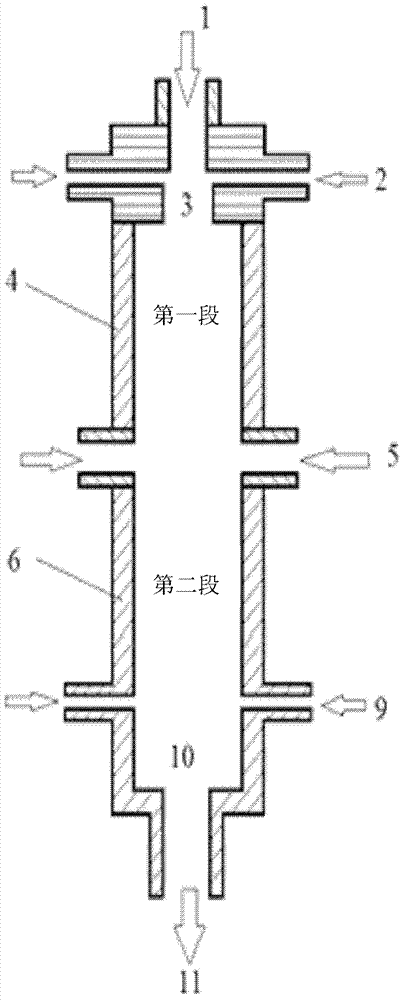
[0103] Its schematic is shown in figure 1 The two-stage plasma-pyrolysis coal reactor is used to convert coal into acetylene and other chemicals. The two-stage plasma reactor operates by means of a plasma generator with an input power of 10 kW to 20 MW. like figure 1 As shown, the reactor consists of two straight passages (ie, reaction tubes) 4 and 6, a top inlet for a first heating gas 1, two inlets for pulverized coal and a carrier gas feed 2, and two first inlets for heating gas 1. Two inlets for heating gas 5, two inlets for quenching medium 9 and one outlet 10 for cracking product 11 are composed of pulverized coal and carrier gas feed 2 and first heating gas 1 in the mixing zone 3 of pulverized coal and carrier gas Below the inlet of feed 2 and immediately above the first section 4 of the reaction tube. The walls of the reactor were constructed of copper near the three heating gas inlets and steel in other areas, while the reactor was cooled by water circulating at hi...

Embodiment 2

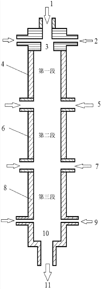
[0119] The experimental procedure described in Example 1 was repeated, except that the two-stage plasma reactor was replaced by a three-stage plasma reactor, wherein the three-stage plasma reactor was assisted by a plasma generator with an input power of 10 kW to 20 MW. come to work. like figure 2 As shown, the reactor consists of three straight channels (ie reaction tubes) 4, 6, and 8, a top inlet for a first heating gas 1, two inlets for pulverized coal and a carrier gas feed 2, Two inlets for the second heating gas 5, two inlets for the third heating gas 7, two inlets for the quenching medium 9, and one outlet 10 for the cracked product 11 are composed of pulverized coal and carrier gas feed 2 and the first The mixing zone 3 of the heating gas 1 is placed under the inlet of the pulverized coal and the carrier gas feed 2, and abuts the upper part of the first section 4 of the reaction tube. The walls of the reactor were constructed of copper near the 5 heating gas inlets ...


PUM

PropertyMeasurementUnit
particle sizeaaaaaaaaaa
thermal decomposition temperatureaaaaaaaaaa

Abstract

The invention discloses a multi-stage plasma carbon material cracking reactor comprising a reaction pipe first section in which a carbon material, carrier gas and a first heating gas are mixed, and in which carbon material pyrolysis is carried out; reaction pipe second to N sections, wherein N is an integer no smaller than 2; at least one carbon material and carrier gas feed inlet positioned on a side of the reaction pipe first section; at least one first heating gas inlet positioned on the top of the reaction pipe first section; at least one second to N heating gas inlets arranged on the sides of the reaction pipe second to N sections, wherein the second to N section heating gas is high-temperature plasma gas; at least one chilling medium inlet used for chilling or freezing reaction products, and at least one chilling product and gas outlet positioned on the bottom or lower part of the reaction pipe last section.

Description

technical field [0001] The present invention relates to a high-energy-efficiency device and method for cracking carbonaceous materials containing volatile components to produce high-yield cracked products, in particular, to a multi-stage plasma cracking carbonaceous material reactor and utilizing the multi-stage plasma reaction A method for pyrolyzing carbonaceous materials in a reactor, and more particularly, also relates to a method for producing acetylene using the multi-stage plasma reactor. Background technique [0002] Typically, the carbonaceous material is heated along with other components, such as hydrogen, by an electric arc device or other suitable heat source known to those of ordinary skill in the art to crack or pyrolyze the carbonaceous material. The composition of the products produced as a result of the decomposition of the carbonaceous material depends on the reaction conditions of the decomposition zone or reaction zone. It is well known that certain spe...

Claims


Application Information

Patent Timeline
Patent Type & Authority Applications(China)
IPC IPC(8): B01J19/08C07C11/24C07C4/04
Inventor 郭屹李轩程易颜彬航吴昌宁苗强
Owner CHNA ENERGY INVESTMENT CORP LTD
Why Eureka
Try Eureka