Fixed bed catalyst preparation method and fixed bed catalyst

A technology of catalyst and fixed bed, which is applied in the field of preparation of fixed bed catalyst and fixed bed catalyst, can solve the problems of high impregnation temperature, low production capacity, poor heat dissipation effect, etc., and achieve good impregnation effect, improved quality, and uniform impregnation Effect

Active Publication Date: 2013-05-08
CHINA PETROLEUM & CHEM CORP
View PDF5 Cites 14 Cited by
  • Summary
  • Abstract
  • Description
  • Claims
  • Application Information

AI Technical Summary

Problems solved by technology

[0009] To sum up, the currently applied hydrogenation catalyst impregnation technology has the following disadvantages: the first production capacity is low
The single batch production capacity of the existing impregnation equipment is between 100-300kg, which is far from meeting the needs of large-scale production of hydrogenation catalysts
If simple capacity expansion is carried out on the basis of the existing impregnation equipment, the quality of the catalyst product will decline, and the impregnation breakage rate of the carrier will be high, which will increase the production cost of the catalyst
Uneven second impregnation
However, due to the relative position of the two ends of the drum, the contact between the carrier and the impregnating liquid is less, resulting in uneven distribution of the impregnated metal.
The third dipping breakage rate is high
At present, the catalyst breakage rate of the impregnation equipment in the prior art is about 2%, the main reason is that the heat dissipation effect is poor during impregnation, and the collision between the carrier and the drum is serious
The fourth cooling effect is poor
At present, the thickness of the material layer in the middle part of the impregnation equipment in the prior art is between 500-800mm, the effect of stirring the material during impregnation is poor, and the adsorption heat is difficult to discharge in time, resulting in high impregnation temperature and affecting the strength of the catalyst

Method used


Image

  • Fixed bed catalyst preparation method and fixed bed catalyst
  • Fixed bed catalyst preparation method and fixed bed catalyst

Examples


Embodiment 1

[0069] This example is used to illustrate the preparation of the hydrogenation catalyst provided by the present invention.

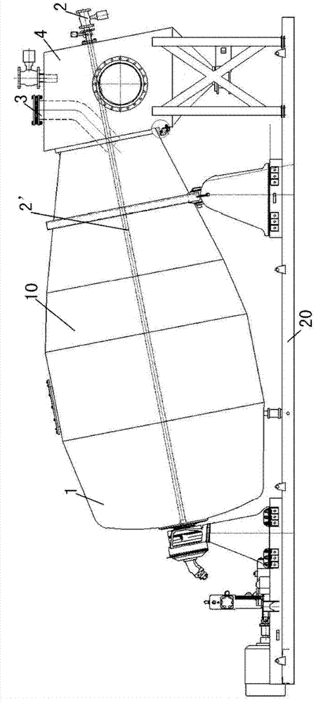
[0070] Prepared as follows figure 1 The macerating machine shown.

[0071] Described macerating machine comprises the cylinder 10 that is inclined to be arranged, driving device (not shown in the figure), feeding device 3, discharge device 4 and base 20, and described cylinder 10 is arranged on the described base 20 obliquely, and the cylinder 10 The tilt angle is 11 degrees. The drum 10 includes a rotatable cylinder body 1, a spraying device 2, and a feed device 3 and a discharge device 4 arranged at one end of the cylinder body 1, and the feed device 3 and the discharge device 4 pass through the cylinder body The mouth of one end of 1 communicates with the inner space of the cylinder 1, and the feed device 3 and the discharge device 4 are respectively sealed and connected with the cylinder 1; the inner diameter of the cylinder 1 is 1.5 meters, and th...

Embodiment 2

[0077] This example is used to illustrate the preparation of the protective layer catalyst provided by the present invention.

[0078] Prepare according to the method of embodiment 1 such as figure 1 The impregnation machine is shown, and its catalyst is prepared, the difference is that the Raschig ring activated alumina carrier S2 (Al 2 o 3The content is 98.5% by weight) (purchased from Yixing Chiba Non-metallic Materials Co., Ltd.) 1000kg is continuously sent into the cylinder 1 through the feed device 3, and vacuumized for 30 minutes, so that the relative pressure (gauge pressure) in the cylinder 1 Be-0.02Mpa, will contain 94 kilograms of ammonium paramolybdate (MoO 3 Content is 81% by weight) and nickel nitrate 72.5 kilograms (NiO content is 25% by weight) aqueous solution 870 liters, under the effect of compressed wind (wind pressure (atomization pressure) is 0.5MPa), at 25 ℃, after spraying The pipe body 2' and the nozzle of the device 2 spray the above-mentioned aque...

Embodiment 3

[0082] This example is used to illustrate the preparation of the anthraquinone hydrogenation catalyst provided by the present invention.

[0083] Prepare according to the method of embodiment 1 such as figure 1 The impregnation machine is shown, and its catalyst is prepared, the difference is that the cylindrical activated alumina carrier S3 (Al 2 o 3 Content is 98.5% by weight) (purchased from Sinopec Catalyst Changling Branch Company) 1000kg is sent into cylinder 1 continuously through feeding device 3, and vacuumized for 30 minutes, so that the relative pressure (gauge pressure) in cylinder 1 is- 0.02Mpa, 800 liters of chloropalladium acid aqueous solution containing 2.2 kilograms of palladium will be passed through the spray device 2 under the effect of compressed air (wind pressure (atomization pressure) is 0.4MPa) by the spray device 2 The pipe body 2' and the nozzle of 2 spray the above-mentioned aqueous solution in an atomized state onto the forming carrier S3 in the...


PUM

PropertyMeasurementUnit
thicknessaaaaaaaaaa
angleaaaaaaaaaa
lengthaaaaaaaaaa

Abstract

The invention discloses a fixed bed catalyst preparation method and a fixed bed catalyst. The method comprises that a molded carrier contacts a metal compound solution in an impregnation machine, and the molded carrier after contacting is dried and calcined, wherein the impregnation machine comprises an obliquely-arranged roller (10), the roller (10) comprises a rotatable cylinder (1) and a spray device (2), the inner wall of the cylinder (1) is provided with a spiral blade, and the spray device (2) is fixedly arranged and extends into the internal space of the cylinder (1). According to the method, a molded carrier is conveyed into the cylinder (1), and a metal compound solution is sprayed on the molded carrier with the spray device (2). With the method, the fixed bed catalyst with characteristics of good impregnation uniformity and low impregnation breaking rate can be obtained, automatic catalyst impregnation control can be achieved, production cost can be reduced, and requirements of large-scale industrial production can be met.

Description

technical field [0001] The invention relates to a preparation method of a catalyst for a fixed bed and a catalyst for a fixed bed prepared by the method. Background technique [0002] Due to the rapid expansion of the scale of refinery hydrogenation units, the domestic demand for hydrogenation catalysts continues to grow rapidly. On the one hand, it is necessary to expand the production capacity of hydrogenation catalysts, and on the other hand, it is necessary to provide better quality hydrogenation catalyst products to meet the market demand for environmentally friendly energy. [0003] The impregnation method is the most common method for producing hydrogenation catalysts. By contacting the catalyst carrier with the impregnating liquid, a certain amount of active components enter into the micropores of the catalyst carrier. The active component penetrates and diffuses to the inner wall of the pore channel, and then undergoes adsorption, deposition or ion exchange with t...

Claims


Application Information

Patent Timeline
Patent Type & Authority Applications(China)
IPC IPC(8): B01J23/888B01J23/883B01J23/44B01J23/42
Inventor 于向真梁维军许德坤成建和王绍北宋志东邓风华李翔斌戴源昌
Owner CHINA PETROLEUM & CHEM CORP
Why Eureka
Try Eureka