Self-adsorption air foam-based foam dust suspension system for tunneling machine

A technology of air foaming and roadheading machines, which is applied in the fields of slitting machinery, earthwork drilling and mining, etc. It can solve the problems of reducing system stability, reliability, low foam utilization rate, and increasing system complexity, so as to improve the efficiency of foam dust reduction , simple structure, and the effect of improving the utilization rate

Inactive Publication Date: 2015-03-04
CHINA UNIV OF MINING & TECH
View PDF10 Cites 0 Cited by
  • Summary
  • Abstract
  • Description
  • Claims
  • Application Information

AI Technical Summary

Problems solved by technology

However, the current foam dust suppression system used in fully mechanized excavation working faces all adopts the compressed air foam production method, that is, the compressed air pipeline is laid to press the compressed air into the foam generator to mix and foam with the foaming liquid, which increases the complexity of the system. It brings great inconvenience to debugging and operation, reduces the stability and reliability of system operation, and the foaming rate is low
In addition, under the action of press-in ventilation air flow, high-concentration dust is distributed on the return air side of the excavation, and the dust concentration on the air intake side is lower. However, the existing foam dust suppression system fails to distribute to the air intake side, return air The foam volume of the foam nozzles on the side is combined with the dust concentration in the area, that is, the same amount of foam is distributed to them, which not only reduces the dust suppression effect, but also causes low foam utilization.

Method used


Image

  • Self-adsorption air foam-based foam dust suspension system for tunneling machine
  • Self-adsorption air foam-based foam dust suspension system for tunneling machine
  • Self-adsorption air foam-based foam dust suspension system for tunneling machine

Examples


Embodiment Construction

[0012] An embodiment of the present invention will be further described below in conjunction with accompanying drawing:

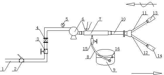
[0013] Such as figure 1 As shown, the present invention is based on self-suction air foaming roadheader foam dust suppression system, which is mainly composed of pressurized water pipeline 1, switch ball valve 2, flow regulating valve 3, mechanical flow meter 4, shock-resistant pressure gauge 5, air-driven liquid pressurization The pump 6 and the self-priming air swirl foaming device 7 are composed; the pressure water pipe 1 is connected to the water supply pipeline extending to the platform of the roadheader body through the quick plug joint, and the switch ball valve 2, the flow regulating valve 3, the mechanical flow rate Meter 4, shock-resistant pressure gauge 5, and gas-driven liquid booster pump 6 are sequentially arranged on the pressure water pipeline 1, and a self-priming air swirl foaming device 7 is provided at the outlet of the gas-driven liquid...


PUM


Abstract

The invention discloses a self-adsorption air foam-based foam dust suspension system for a tunneling machine, and is particularly suitable for dust control of underground coal mine fully-mechanized excavating working faces. The system mainly comprises a water pressing pipeline, a flow adjusting valve, a mechanical flowmeter, a shock-proof pressure meter, a gas-driven liquid booster pump, a foaming agent container, a self-adsorption air rotational flow foaming device, a liquid adsorption pipe, a foam conveying main pipe, a foam conveying branch pipe and a foam spray head, wherein high-pressure water flow passes through an inlet of the self-adsorption air rotational flow foaming device to form high-speed jet, and air in the environment and the foaming agent are automatically sucked, so that the full mixing of the foaming agent, water and air is realized to further generate dust suspension foam; and the foam is sprayed to a dust-generation slicing part of the tunneling machine by the foam spray head. The system does not include electrical elements, is safe, reliable, easy to operate and maintain, and small in water consumption amount, and has wide practicability; and the dust control effect of the fully-mechanized excavating working faces can be improved.

Description

technical field [0001] The invention relates to a roadheader foam dust suppression system based on self-suction air foaming, and is especially suitable for controlling the cutting dust of the roadheader. Background technique [0002] The high-concentration dust generated during the cutting of coal and rock mass by roadheaders is not only one of the main disasters that restrict the safety of coal mine production, but also the most important occupational hazard that endangers the health of tunneling workers. Compared with conventional dust suppression media such as water spray used in tunneling working faces, foam has the characteristics of large contact surface, good wettability and strong adhesion, which can significantly improve the dust suppression effect. However, the current foam dust suppression system used in fully mechanized excavation working faces all adopts the compressed air foam production method, that is, the compressed air pipeline is laid to press the compress...

Claims


Application Information

Patent Timeline
Patent Type & Authority Patents(China)
IPC IPC(8): E21C35/22
Inventor 王德明王和堂王庆国汤研贾志强
Owner CHINA UNIV OF MINING & TECH
Why Eureka
Try Eureka