
System utilizing absorption heat pump to recover exhaust steam waste heat of power station and heat boiler supply water

An absorption heat pump and heating boiler technology, applied in heat recovery systems, feed water heaters, energy-saving heating/cooling, etc., can solve the problems of increasing initial investment, high initial investment of electric heat pumps, and reducing heat utilization efficiency, etc., to reduce equipment Investment, avoiding irreversible losses, and the effect of short investment return time

Active Publication Date: 2013-05-08
浙江和帆企业管理有限公司
View PDF7 Cites 14 Cited by
  • Summary
  • Abstract
  • Description
  • Claims
  • Application Information

AI Technical Summary

Problems solved by technology

[0007] In addition, there is also the technology of using the heat pump to recover the circulating water heat of the condenser of the power station to heat the condensed water, but the disadvantage of this technology is that it is for indirect heat exchange, which increases the initial investment and reduces the heat utilization efficiency; and the heat-absorbing link is not Directly absorb the waste heat of the exhaust steam, but absorb the waste heat of the cooling circulating water of the condenser; and the heating link, instead of directly heating the condensed water, set up a heat exchanger for indirect heating; in addition, the heat pump adopts an electric heat pump instead of an absorption type Heat pumps; relatively speaking, electric heat pumps need to consume high-quality electric energy to drive, and require a special power distribution cabinet; from the perspective of primary energy utilization, the efficiency of electric heat pumps and absorption heat pumps is similar, but the initial stage of electric heat pumps relatively higher investment

Method used


Image

  • System utilizing absorption heat pump to recover exhaust steam waste heat of power station and heat boiler supply water
  • System utilizing absorption heat pump to recover exhaust steam waste heat of power station and heat boiler supply water
  • System utilizing absorption heat pump to recover exhaust steam waste heat of power station and heat boiler supply water

Examples


Embodiment Construction

[0030] The technology of the present invention will be described below in conjunction with specific embodiments.

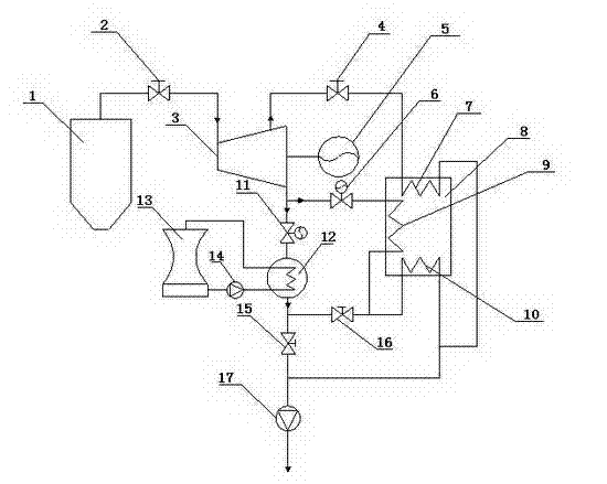
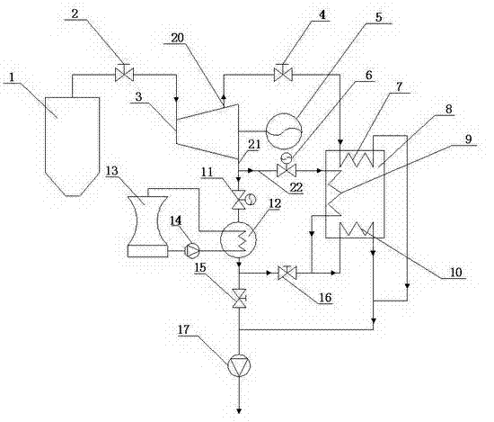
[0031] figure 1 It is a schematic diagram of the pipeline connection structure of the absorption heat pump recovery power station exhaust steam waste heat and heating boiler feed water system of a preferred embodiment of the present invention, figure 2 for figure 1Schematic diagram of pipeline connection and fluid flow of the system when the generator set and the absorption heat pump are running in the embodiment.

[0032] Such as figure 1 , figure 2 As shown, the absorption heat pump of the present invention recovers waste heat from power plant exhaust and heats boiler feed water, including a generator set and an absorption heat pump. The generator set includes a boiler 1 that generates high-temperature and high-pressure steam, a generator 5, and a generator that rotates to drive the generator 5 to generate electricity. Steam turbine 3 , condenser 12 , c...


PUM


Abstract

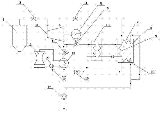
The invention relates to a system utilizing an absorption heat pump to recover exhaust steam waste heat of a power station and heat boiler supply water. The system comprises a generator set and the absorption heat pump. The generator set comprises a boiler, an electric generator, a steam turbine, a steam condenser and a cooling tower, wherein the boiler is capable of generating high-temperature high-pressure steam, the steam turbine rotates to drive the electric generator to generate power, and the steam condenser and the cooling tower utilize steam or part of the steam behind the steam turbine to cool. The absorption heat pump comprises a generator, an evaporator, an absorber and a condenser. When the generator set and the absorption heat pump are in use, after the high-temperature high-pressure steam generated from the boiler passes through the steam turbine, one part of exhaust steam passes through the evaporator of the absorption heat pump, extracted steam of the steam turbine passes through the generator of the absorption heat pump, the absorption heat pump is driven to run by the extracted steam of the generator set, the exhaust steam waste heat of the generator set is comprehensively utilized by the absorption heat pump so as to improve utilization rate of the waste heat, and the heat energy after running of the absorption heat pump is utilized to preheat the boiler supply water of the generator set.

Description

technical field [0001] The invention belongs to the technical field of HVAC recovery, and in particular relates to a system which utilizes an absorption heat pump to recover waste heat from power station exhaust and heat boiler feed water. Background technique [0002] The power station cycle is a steam power cycle developed on the basis of the Rankine cycle. It includes four main equipments: boiler, steam turbine, condenser and feed water pump. The water is pressurized by the feed pump and then sent to the boiler, where it is heated into high-temperature and high-pressure steam, enters the steam turbine to expand and do work, and is discharged into the condenser to condense at a constant pressure to form condensed water, which is then re-sent into the boiler by the feed water pump to start a new cycle. cycle. [0003] Even if measures such as ultra-high steam parameters, reheating and reheating are adopted in the modern steam power cycle, its efficiency still does not exc...

Claims


Application Information

Patent Timeline
Patent Type & Authority Applications(China)
IPC IPC(8): F22D1/00F01K11/02
CPCY02B30/52
Inventor 尹斌
Owner 浙江和帆企业管理有限公司
Learn More