
Distributed optical fiber sensing device and method based on Brillouin Er-doped fiber laser

A technology of distributed optical fiber and erbium-doped optical fiber, applied in the direction of using optical devices, using optical devices to transfer sensing components, measuring devices, etc., can solve complex frequency locking and frequency discrimination technology, laser frequency difference, multilateral sidebands, etc. Problems, Achieve the effect of compact system structure, reduce system cost and simplify system structure

Inactive Publication Date: 2013-05-08
NAT UNIV OF DEFENSE TECH
View PDF4 Cites 32 Cited by
  • Summary
  • Abstract
  • Description
  • Claims
  • Application Information

AI Technical Summary

Problems solved by technology

One solution is to use two lasers as pump light and probe light respectively. The frequency difference of the output light of the two lasers can be adjusted around the Brillouin frequency shift of the fiber. The disadvantage of this solution is that the frequency of the laser itself is stable. The performance requirements are relatively high, and complex frequency locking and frequency discrimination techniques are required to control and measure the frequency difference between the two lasers; the other is the method of using electro-optic modulator microwave frequency shifting, which is widely used at present, and the same light source is used to obtain the required Pump light and probe light, but this solution requires an expensive high-speed electro-optic modulator and a tunable high-frequency microwave signal source, and the frequency shift of the electro-optic modulator has the problems of unstable output optical power and multiple sidebands

Method used


Image

  • Distributed optical fiber sensing device and method based on Brillouin Er-doped fiber laser
  • Distributed optical fiber sensing device and method based on Brillouin Er-doped fiber laser
  • Distributed optical fiber sensing device and method based on Brillouin Er-doped fiber laser

Examples


Embodiment Construction

[0021] The present invention will be further described below in conjunction with accompanying drawing.

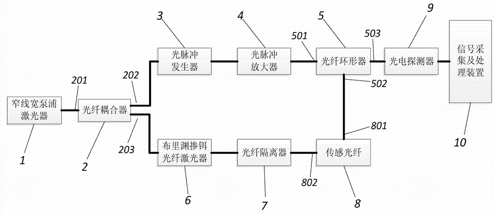
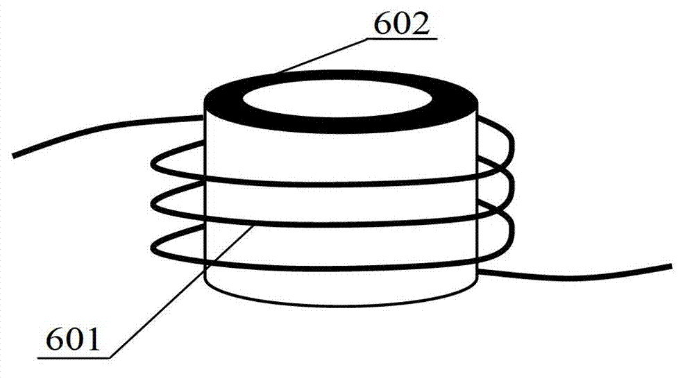
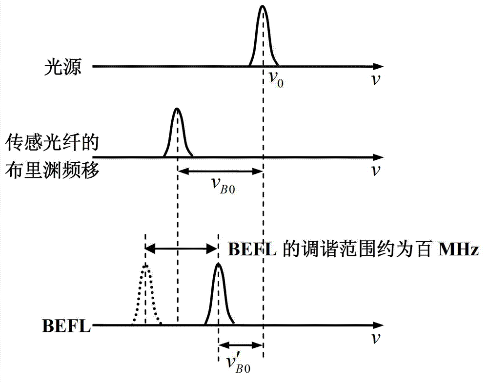
[0022] see figure 1 , the present invention consists of a narrow linewidth pump laser 1, a fiber coupler 2, an optical pulse generator 3, an optical pulse amplifier 4, an optical fiber circulator 5, a Brillouin erbium-doped fiber laser 6, an optical fiber isolator 7, and a sensing fiber 8. A photodetector 9 and a signal acquisition and processing device 10 are formed. The output light of the narrow-linewidth pump laser 1 is divided into two beams through the fiber coupler 2, and one beam is modulated into pulsed light by the optical pulse generator 3, and then the power is amplified by the optical pulse amplifier 4, and then passed through the optical fiber circulator 5 Inject into one end of the sensing fiber 8; another bundle pumps the Brillouin erbium-doped fiber laser 6, the output light of the laser passes through the fiber isolator 7 and injects into the other end of...


PUM


Abstract

The invention relates to distributed optical fiber sensing technology and provides a distributed optical fiber sensing device and a method based on a Brillouin Er-doped fiber laser. The distributed optical fiber sensing device and the method based on the Brillouin Er-doped fiber laser comprise a narrow linewidth pump laser, an optical fiber coupler, an optical pulse generator, an optical pulse amplifier, an optical fiber amplifier, an optical fiber circulator, sensing optical fibers, a Brillouin Er-doped fiber laser, an optical fiber isolator, an photoelectric detector and a signal collecting and processing device. Brillouin gain optical fibers of the Brillouin Er-doped fiber laser are wound on piezoelectric ceramic, and Brillouin frequency shift is changed through adjusting temperature of the Brillouin gain optical fibers and / or convergent-divergent of the piezoelectric ceramic. According to the distributed optical fiber sensing device and the method based on the Brillouin Er-doped fiber laser, pump light needed by a Brillouin optical time domain analysis meter (BOTDA) and detecting light which is provided with the Brillouin frequency shift and is tunable are obtained with the same light source, and no additional laser or high-speed modulator and microwave modulating source of the high-speed modulator is needed. The system cost is lowered, the system structure is simplified, and the system structure is enabled to be compact and convenient to pack.

Description

technical field [0001] The invention relates to distributed optical fiber sensing technology, in particular to a distributed optical fiber sensing technology based on Brillouin scattering. Background technique [0002] Distributed optical fiber sensors use the optical fiber itself as both the sensing body and the transmission medium, and can accurately measure information such as stress, temperature, vibration, and damage at any point along the optical fiber, and realize long-distance, continuous distributed monitoring. Based on the outstanding characteristics of distributed optical fiber sensors, it is widely used in the security of national defense and the safety of people's lives and property, oil and gas transportation pipelines, power networks, urban infrastructure, structural health monitoring of large buildings, early warning of fires and landslides, and aircraft, It has significant technical advantages and broad application prospects in damage monitoring of ships and...

Claims


Application Information

Patent Timeline
IPC IPC(8): G01D5/36G01B11/16G01K11/32G01K11/322
Inventor 孟洲周会娟涂晓波陈默孙世林孙乔宋章启张学亮熊水东
Owner NAT UNIV OF DEFENSE TECH
Learn More