Direction-controllable laser device system

A technology for lasers and laser arrays, applied in laser devices, devices for controlling laser output parameters, semiconductor laser devices, etc., can solve the problems of increased array unit spacing, complex structure, huge control system, etc., and achieve precise adjustment of deflection angle, The effect of increasing the deflection angle and improving the stability

Active Publication Date: 2013-05-08
苏州康冠光电科技有限公司
View PDF4 Cites 15 Cited by
  • Summary
  • Abstract
  • Description
  • Claims
  • Application Information

AI Technical Summary

Problems solved by technology

In the patent WO9924866-A, ZHU Y, ZHU R and others proposed that according to a certain statistical law, the array units are arranged irregularly, which can increase the spacing of some array units. Due to the irregular arrangement of the units, the side lobes are transformed into noise, thereby highlighting the main Beam, this method has improved the processing technology, but there is no essential breakthrough in the research of optical phased array technology
In addition, due to the large number of units in the optical phased array, the control system is huge and the structure is complex. When the geometric size of the radiation aperture and the number of array units are fixed, in order to reduce the control lines, Terry A. Dorschner et al. proposed to divide the aperture array into sub-arrays, and The control lines of the corresponding array units of the sub-arrays are connected in parallel to realize the "fine / coarse" beam driving method, but this method has a small range of beam driving angles and discontinuous driving angles

Method used


Image

  • Direction-controllable laser device system
  • Direction-controllable laser device system
  • Direction-controllable laser device system

Examples


Embodiment Construction

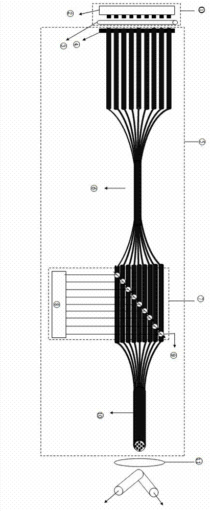
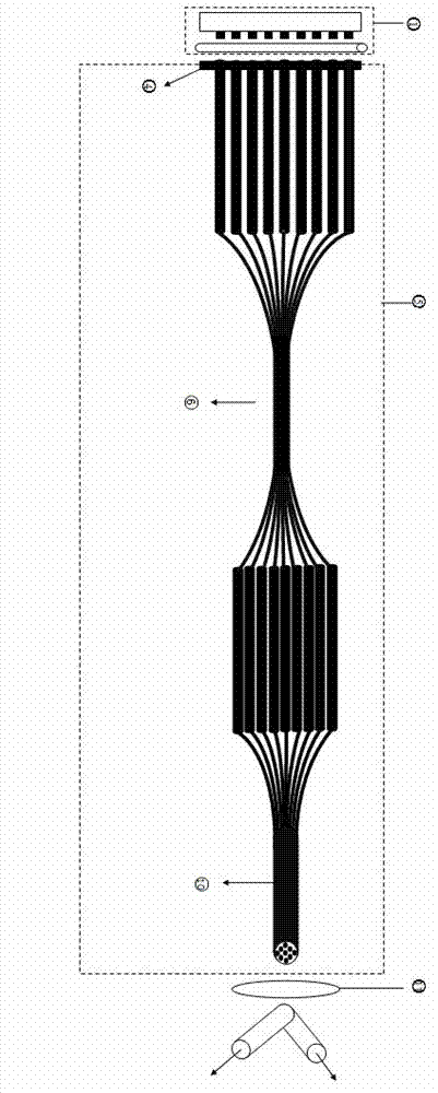
[0032] figure 1 It is the device diagram of the phased array laser system of the present invention. The invention uses a semiconductor array laser as a laser source, which has high conversion efficiency and small volume; the optical fiber tapered array is used as a waveguide, which has good light guiding performance, does not change the properties of the beam, has low loss, and has good flexibility; using a self-adjusting phase-locking method, Developed a new type of combined laser (such as figure 2 shown), and on this basis, each waveguide unit is phase-controlled to achieve fast and flexible beam direction driving. In particular, with the development of semiconductor lasers and the development of more waveguide devices, the present invention has great room for development.

[0033] Firstly, the manufacturing method of the fiber taper array of the present invention is introduced. The fiber taper array is composed of three parts: alignment section I, taper bundle coupling s...


PUM


Abstract

The invention discloses a direction-controllable laser device system and belongs to the technical field of laser devices. The direction-controllable laser device system comprises a laser source, a waveguide and a phase control system, wherein the laser source, the waveguide and the phase control system are sequentially connected. The laser source comprises a semi-conductor laser device array (1) and a microlens array (2), wherein the semi-conductor laser device array supplies a power source for the direction-controllable laser device system, each luminous unit is plated with an antireflection film, and light emitted by the luminous units of the semi-conductor laser device array is shaped and coupled into optical fibers through the microlens array. The waveguide is an optical fiber tapering array which is developed aiming at the direction-controllable laser device system. The optical fiber tapering array comprises an alignment section I, a tapering bundling coupling section II and a tapering rearrangement section III, wherein the alignment section I, the tapering bundling coupling section II and the tapering rearrangement section III are sequentially connected. The phase control system comprises a titanium diffusion niobic acid lithium integrated optical waveguide phase shifter. The direction-controllable laser device system enables the angle of deflection to be more accurate and adjustable, and stability of the direction-adjustable laser device system also can be improved.

Description

technical field [0001] The invention relates to a direction-controllable laser system, in particular to a new all-fiber combined laser system. In addition, this system can realize fast and flexible beam direction driving based on optical phased array laser technology, and its driving angle range is large and the driving angle is continuous. Background technique [0002] According to the needs of industry, military and other fields, the future development trend of lasers is: high energy, high beam quality, high efficiency, flexible and compact. However, as the pump power increases, high-power solid-state lasers have thermal lens effects, and fiber lasers have nonlinear effects and damage thresholds, so their development space has certain limits. Considering that the array unit of the semiconductor array laser with small size, high efficiency and cheap price can be expanded, the power of the laser system can be effectively improved; the transmission mode of the optical fiber ...

Claims


Application Information

Patent Timeline
Patent Type & Authority Applications(China)
IPC IPC(8): H01S5/40H01S5/06
Inventor 杨登才王大勇杨作运赵思思
Owner 苏州康冠光电科技有限公司
Why Eureka
Try Eureka