Electrical heating rod device

An electric heating rod and heating tube technology, which is applied to heating elements, ohmic resistance heating parts, heating element shapes, etc., can solve the problems of easy deflection, large flexibility of heating rods, and large lengths, etc., and achieves high heat flow density, The effect of low cost and simple structure

Active Publication Date: 2013-05-08
TSINGHUA UNIV
View PDF6 Cites 12 Cited by
  • Summary
  • Abstract
  • Description
  • Claims
  • Application Information

AI Technical Summary

Problems solved by technology

But the hidden danger of this method is: when the length and diameter of the heating rod are relatively large, the force on the heating rod can be regarded as a double-ended cantilever beam model, which makes the heating rod itself very flexible and easy to bend. At this time, on the one hand, The effect of thermal expansion will cause the length of the heating rod to increase significantly when it is working. If the thermal expansion of the heating rod cannot be well compensated, it will easily cause the heating rod to bend. The heating rods contact and short circuit; on the other hand, the strong magnetic field generated by the high current intensity will also cause repulsion or attraction between the electric heating rods, which will also cause the heating rods to bend and contact short circuit, and the heating rods will not work normally until they burn out or other dangers

Method used


Image

  • Electrical heating rod device
  • Electrical heating rod device

Examples


Embodiment Construction

[0022] The electric heating rod device proposed by the present invention is described in detail as follows with reference to the accompanying drawings and embodiments.

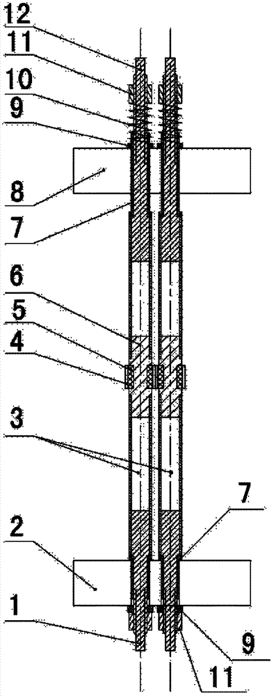
[0023] The electric heating rod device of the present invention includes one or a plurality of electric heating rods arranged side by side, and this embodiment takes two electric heating rods as an example. Such as figure 1 As shown, in an electric heating rod device according to an embodiment of the present invention, the electric heating rods include:

[0024] Multi-section heating pipe 3 (the present embodiment is 2 sections, but not limited thereto), the heating pipe is an energized metal pipe directly immersed in the heated fluid, which can be made of 304 stainless steel pipe or 306 stainless steel pipe, and is used to pass through it. The current is converted into heat energy, and the wall thickness and length of each section of the heating tube are reasonably arranged according to the total length of t...


PUM


Abstract

The invention discloses an electrical heating rod device, and relates to the technical field of reactor thermohydraulics experiments and reactor in-pile electric auxiliary heating. The electrical heating rod device comprises one electrical heating rod or a plurality of electrical heating rods arranged in parallel. Each electrical heating rod comprises a plurality of sections of heating tubes, a plurality of intermediate transition connectors and two end connectors, wherein the plurality of section of hating tubes are used for transforming electric currents passing through the heating tubes into heat energy, the plurality of intermediate transition connector are connected between two adjacent sections of heating tubes and used for achieving the electrical connection of two adjacent sections of heating tubes, and the two end connectors are respectively arranged at one ends of two sections of heating tubes arranged at two ends, and used for guiding electrical currents into the heating tubes. The electrical heating rod device adapts to the requirements of the external diameters, the length, the pitches and the like of various heating rods, and is high in heat flow density, simple in structure, reliable and low in cost.

Description

technical field [0001] The invention relates to the technical field of reactor thermohydraulic experiments and electric auxiliary heating inside the reactor, in particular to an electric heating rod device. Background technique [0002] During the heat release process of the core fuel rods of a nuclear reactor, the surface of the fuel rods has a high heat flux density. At the same time, the distribution of heat flux along the length of the fuel rod is often sinusoidal, which is a nonlinear distribution. In engineering design, it is usually necessary to simulate the real situation of the flow and heat transfer of the cooling medium inside the core by simulating the thermal-hydraulic experiments of the nuclear reactor, and verify the difference from the design conditions to avoid flow instability, Phenomena such as flow pulsation or film boiling can accurately predict and prevent nuclear reactor operating accidents. How to simulate the reactor core more realistically has alw...

Claims


Application Information

Patent Timeline
Patent Type & Authority Applications(China)
IPC IPC(8): H05B3/06H05B3/40
Inventor 孙艳飞杨星团刘洋任成刘志勇贾海军
Owner TSINGHUA UNIV
Why Eureka
Try Eureka