

Method and apparatus for mechanical defoaming of coking tower
A mechanical defoaming and coking tower technology, applied in the petrochemical field, can solve the problems of high cost and complex composition of raw materials, and achieve the effects of small footprint, low operating cost and long service life
Active Publication Date: 2013-05-15
CHINA PETROLEUM & CHEM CORP +1
View PDF4 Cites 4 Cited by
- Summary
- Abstract
- Description
- Claims
- Application Information
AI Technical Summary
Problems solved by technology
It uses polyether or modified polyether polymers, high-carbon alcohol mixtures, high-carbon alcohol fatty acid esters or fatty amides, hydrocarbonated oils and other raw materials to make defoamers. Although it has a certain defoaming effect, the composition of raw materials is complex ,higher cost
Method used
View moreImage
Smart ImageViewing Examples

Examples
Embodiment 1
[0027] A centrifugal defoamer is installed on the top of the coke tower. The length of the foam suction pipe of the centrifugal defoamer penetrates into the coke tower is 10% of the height of the coke tower. When the foam layer reaches the foam suction pipe, the centrifugal defoamer is started. The properties of the test raw materials are shown in Table 1, and the process operating conditions and test results are shown in Table 2. The embodiment mainly investigates that in the absence of a defoamer, the normal operation cycle of the coke drum can also be achieved by relying on a centrifugal defoamer.
Login to View More PUM
 Abstract
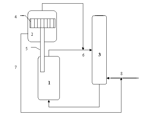
The invention provides a method and an apparatus for mechanical defoaming of a coking tower. According to the invention, a novel centrifugal defoamer is arranged, a foam suction tube of the centrifugal defoamer extends into a foam layer of a coke tower, and impellers rotating at a high speed break sucked foam; gas in the defoamer enters into a coking separation tower with oil gas at the top of the coke tower, liquid in the defoamer converges at the bottom of the defoamer along the wall of the defoamer, and the liquid can be used as cycle oil or can enter into the coking separation tower after separation of coke powder. With the method and the apparatus provided by the invention, a defoaming agent added in a coking process can be omitted or reduced, and no unfavorable influence is exerted on subsequent processing of a coked liquid product.
Description
technical field [0001] The invention relates to a method and device for mechanically defoaming a coking tower, belonging to the technical field of petrochemical industry. Background technique [0002] In recent years, due to the increasing shortage of petroleum resources in the world and the increasing demand for energy in various countries, people have paid more and more attention to the processing and utilization of residual oil. As a kind of decarbonization technology, residual oil coking process has the advantages of low investment and low operating cost, and has been widely developed. [0003] During the operation of delayed coking, as the feed and reaction time increase, the coke surface in the coke tower will gradually increase, and the foam layer in the tower will also approach the top of the tower. It will affect the stability of the subsequent equipment operation and reduce the effective volume of the coke drum. Therefore, in order to solve the problem of the fo...
Claims
Login to View More Application Information
Patent Timeline
 IPC IPC(8): C10G55/04C10G9/00B01D19/04
Inventor 王喜彬曲涛曹春清刘雪玲郭蓉刘建宇曾榕辉
Owner CHINA PETROLEUM & CHEM CORP