Combined process of hydrotreatment and delayed coking for residual oil
A technology of delayed coking and hydrotreating, which is applied in the fields of hydrotreating process, petroleum industry, and hydrocarbon oil treatment, etc. It can solve the problems of reducing the processing capacity of the unit and low thermal cracking temperature, so as to reduce the processing load, delay the tendency of coking, The effect of reducing foam generation
- Summary
- Abstract
- Description
- Claims
- Application Information
AI Technical Summary
Problems solved by technology
Method used
Image
Examples
Embodiment 1
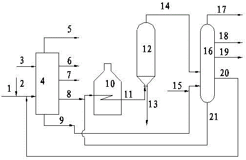
[0033] In this example, vacuum residue, 10% by weight coker gas oil (accounting for vacuum residue) and hydrogen are mixed together, and enter the residue hydrogenation unit for reaction in the presence of a catalyst, and the hydrogenation reaction product is separated to obtain the generated gas , naphtha, diesel oil, hydrogenated tail oil (including hydrogenated vacuum gas oil and hydrogenated vacuum residue, both of which enter the coking tower evenly in the same proportion), separate the coking products to obtain coking dry gas, coking gasoline, Coker diesel, coker gas oil and needle coke, where coker gas oil is recycled to hydrotreating unit. Operating conditions, material balance and properties of some products are shown in Table 2, Table 3 and Table 4, respectively.
[0034] It can be seen from Table 3 and Table 4 that the yield of hydrogenated tail oil (greater than 350°C) obtained after hydrotreating is 86.8% by weight; the yield of coked gasoline and coked diesel oil...
Embodiment 2
[0036] In this example, vacuum residue, 30% by weight coker gas oil (accounting for vacuum residue) and hydrogen are mixed together, and enter the residue hydrogenation unit for reaction in the presence of a catalyst, and the hydrogenation reaction product is separated to obtain the generated gas , naphtha, diesel oil, hydrogenated tail oil (including hydrogenated vacuum gas oil and hydrogenated vacuum residue, both of which enter the coking tower evenly in the same proportion), separate the coking products to obtain coking dry gas, coking gasoline, Coker diesel, coker gas oil and needle coke, where coker gas oil is recycled to hydrotreating unit. Operating conditions, material balance and properties of some products are shown in Table 2, Table 3 and Table 4, respectively.
[0037] It can be seen from Table 1 that the viscosity of the vacuum residue raw material after adding coking gas oil is significantly reduced, and the viscosity at 100°C is from nearly 1285mm 2 / s down to...
Embodiment 3
[0047] According to the method described in Example 1, the hydrogenated vacuum gas oil is injected into 80% of the total feed of the hydrogenated vacuum gas oil in the entire feed cycle in the first 40% of the coking tower feed cycle. The results show that the circulation of coking gas oil can be reduced by about 20% in the whole cycle, indicating that the single-pass cracking rate of hydrotreated vacuum gas oil in the coking tower is improved.
PUM
 Abstract
Description
Claims
Application Information
 - R&D
- Intellectual Property
- Life Sciences
- Materials
- Tech Scout
- Unparalleled Data Quality
- Higher Quality Content
- 60% Fewer Hallucinations
Browse by: Latest US Patents, China's latest patents, Technical Efficacy Thesaurus, Application Domain, Technology Topic, Popular Technical Reports.
© 2025 PatSnap. All rights reserved.Legal|Privacy policy|Modern Slavery Act Transparency Statement|Sitemap|About US| Contact US: help@patsnap.com

