
Ultra-high-speed micro-hole tool drilling device and system

A micro-hole, ultra-high-speed technology, used in manufacturing tools, boring/drilling, drilling/drilling equipment, etc. Workpiece quality, drill life and other issues, to achieve the effect of high cutting accuracy, strong applicability, and extended drill life

Active Publication Date: 2015-12-23
SHENZHEN ZHU GUANGBO MACHINERY TECH
View PDF6 Cites 0 Cited by
  • Summary
  • Abstract
  • Description
  • Claims
  • Application Information

AI Technical Summary

Problems solved by technology

[0002] The traditional drilling, milling and milling tool machine drives the pulley shaft through the rotation of the transmission shaft, and drives the drill bit below to process. The hole precision of the workpiece is low. One is because the motor itself has a large mechanical vibration, and the other is because of the friction and vibration between the workpiece and the drill. Large, generally above 20 microns of vibration and beating, there is no good support body and displacement force in the transmission, so the vibration of the drill bit and the workpiece and the concentricity of the drill clamp and the clamping bit are not accurate, and it is easy to get stuck or stalled and broken bits
Traditional machine tools directly affect the quality of the workpiece and the life of the drill bit, severely restricting the processing of high-precision products

Method used


Image

  • Ultra-high-speed micro-hole tool drilling device and system
  • Ultra-high-speed micro-hole tool drilling device and system

Examples


Embodiment Construction

[0021] Embodiments of the present invention will be described in detail below in conjunction with the accompanying drawings. It should be emphasized that the following description is only exemplary and not intended to limit the scope of the invention and its application.

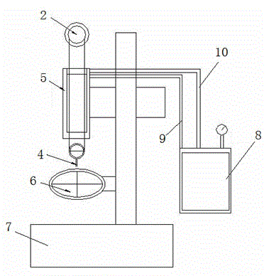
[0022] see figure 1 , in some embodiments, an ultra-high-speed micro-hole tool drilling system includes an ultra-high-speed micro-hole tool drilling device, a machine base 7, a workpiece clamping table 6 and a medium supply device, and the medium supply device is connected to The medium input port of the ultra-high-speed micro-hole tool drilling device, the processed workpiece is installed on the processed workpiece clamping platform 6, and the ultra-high-speed micro-hole tool drilling device and the processed workpiece clamping platform 6 is installed on the base 7.

[0023] Such as figure 1 As shown, preferably, the medium supply equipment is a high-pressure oil station 8, and the high-pressure oil stat...


PUM


Abstract

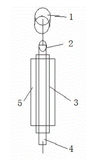
A superspeed micro hole tool drill device comprises a power spindle, a rotating spindle, a clamping head and a drill bit clamped through the clamping head. The power spindle drives the rotating spindle to rotate, and the rotating spindle drives the clamping head and the drill bit to move. The superspeed micro hole tool drill device further comprises a hollow lifting shaft and a supporting fixing sleeve, the lifting shaft is sleeved on the rotating spindle, the supporting fixing sleeve is sleeved on the lifting shaft, the lifting shaft is supported on the supporting fixing sleeve in an air floatation or liquid floatation or magnetic suspension mode, the rotating spindle is supported in the lifting shaft in the air floatation or liquid floatation or magnetic suspension mode, air pressure or hydraulic pressure or magnetic force in the supporting fixing sleeve is controlled according to the processing depth requirements so as to enable the lifting shaft to drive the rotating spindle to rise, and the rotating spindle drives the drill bit to perform rotation and vertical displacement processing. Vibration is small when the device is used for processing superfine holes, processing precision is high, and the service life of the drill bit can be prolonged.

Description

technical field [0001] The invention relates to a drilling, grinding and milling machine tool, in particular to an ultra-high-speed micro-hole tool drilling device. Background technique [0002] The traditional drilling, milling and milling tool machine drives the pulley shaft through the rotation of the transmission shaft, and drives the drill bit below to process. The hole precision of the workpiece is low. One is because the motor itself has a large mechanical vibration, and the other is because of the friction and vibration between the workpiece and the drill. Large, generally above 20 microns of vibration and beating, there is no good support body and displacement force in the transmission, so the vibration of the drill bit and the workpiece and the concentricity of the drill clamp and the clamping bit are not accurate, and it is easy to get stuck or stalled and broken bits. Traditional machine tools directly affect the quality of the workpiece and the life of the dril...

Claims


Application Information

Patent Timeline
Patent Type & Authority Patents(China)
IPC IPC(8): B23B39/00B23B47/04B23B19/02B23B47/18B23B47/00
Inventor 朱光波
Owner SHENZHEN ZHU GUANGBO MACHINERY TECH
Learn More