Oil shale dry distillation device and method

A technology of oil shale and dry distillation, which is applied in special forms of dry distillation, petroleum industry, coking oven, etc., can solve the problems of low oil shale treatment efficiency, high height, and impossibility of oil shale dry distillation, etc., and achieves easy industrial scale-up, Improve dry distillation efficiency, simple and reasonable structure

Inactive Publication Date: 2013-06-12
李伟
View PDF6 Cites 4 Cited by
  • Summary
  • Abstract
  • Description
  • Claims
  • Application Information

AI Technical Summary

Problems solved by technology

[0010] The existing technical data show that most of the existing oil shale retort equipment has the selectivity to the oil shale particle size, and it is impossible to retort the oil shale with a wide particle size range; and the existing oil shale retort equipment is highly Higher, the treatment efficiency of oil shale is not high

Method used


Image

  • Oil shale dry distillation device and method
  • Oil shale dry distillation device and method
  • Oil shale dry distillation device and method

Examples


Embodiment 1

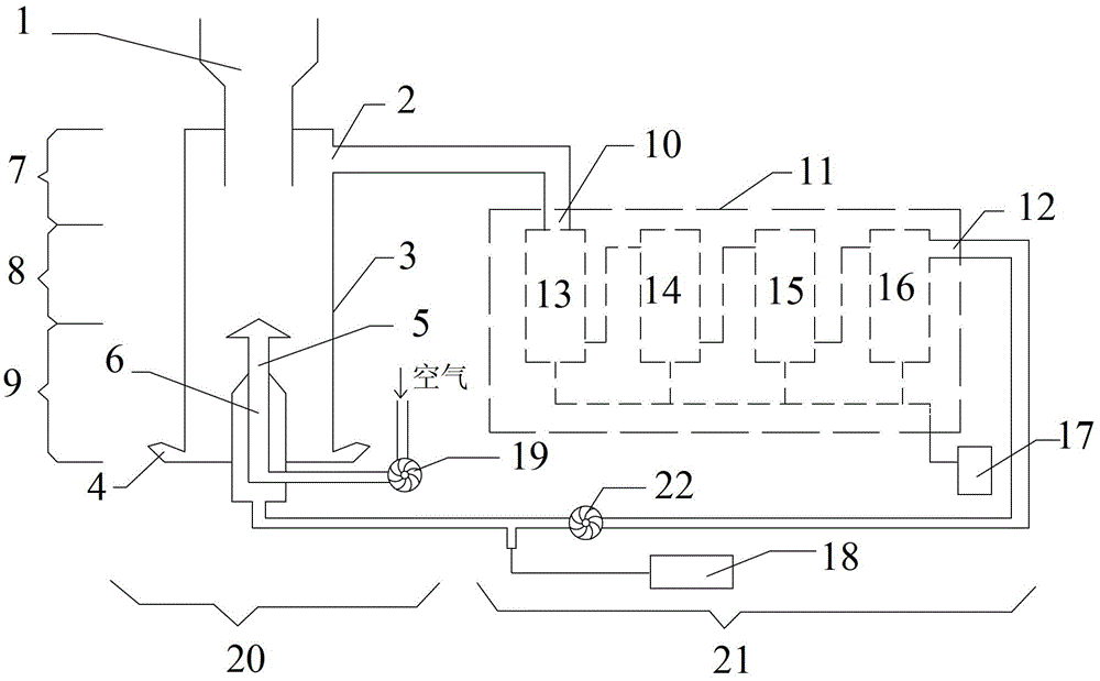
[0052] Such as figure 1 As shown, an oil shale dry distillation device includes an internal combustion dry distillation furnace 20, a spin trap 13, a sprayer 14, a baffle reactor 15 and a centrifuge 16 connected in sequence;

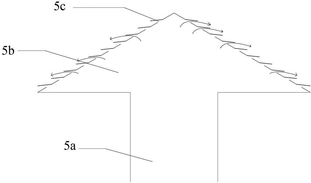
[0053] The internal combustion retort furnace 20 is provided with a charging device 1 at the top, a flue gas outlet 2 at the upper part, and a slag discharge device 4 at the bottom. A gas inlet channel 6 is provided through the bottom of the internal combustion retort furnace 20, and air enters along the axis of the gas inlet channel 6 Channel 5. The furnace wall of the internal combustion retort furnace 20 is an interlayer, and the interlayer is provided with water cooling.

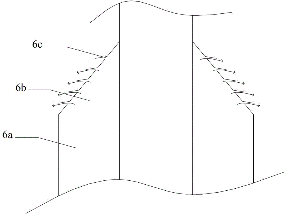
[0054] The gas inlet channel 6 includes a gas gas delivery pipe 6a and a gas spray head 6b. The gas spray head 6b is a cone, and the bottom of the cone is fixed and seamlessly connected with the gas delivery pipe 6a; the cone of the gas spray head 6b The cylinder surface is provided wi...

Embodiment 2

[0059] An oil shale refining method includes the following steps:

[0060] (1) The gas and air enter the internal combustion dry distillation furnace 3 from the bottom of the internal combustion dry distillation furnace 20 under the action of the first air extraction pump 19 and the second air extraction pump 22 respectively, and burn at high temperature to release heat, and the temperature rises to 860±100°C , And keep the furnace temperature at 860±100℃;

[0061] (2) Oil shale particles with a particle size of 0-120mm are fed through the feeding device 1, and the internal combustion retort furnace 20 meets the gas phase that continues to enter the bottom, and retorts under anaerobic conditions to produce flue gas and ash;

[0062] (3) The flue gas enters the gas-liquid separation device such as the cyclone 13, the sprayer 14, the baffle reactor 15 and the centrifuge 16 along the pipeline, and obtains shale oil and gas after separation; shale oil After being collected at the bottom...


PUM

PropertyMeasurementUnit
particle diameteraaaaaaaaaa

Abstract

The invention relates to oil shale dry distillation device and method. The device comprises an internal combustion retort furnace, and an oil-gas separating device, wherein the internal combustion retort furnace is used for distilling oil shale particles; the oil-gas separating device is used for separating oil shale and gas in smoke generated after oil shale combustion; the internal combustion retort furnace comprises a feeding device, a smoke outlet, a furnace body, a slag discharge device, an air inlet channel and a gas inlet channel; the feeding device is arranged on the top of the internal combustion retort furnace; the smoke outlet is formed in the upper part of the internal combustion retort furnace; the slag discharge device is arranged at the bottom of the internal combustion retort furnace; and the air inlet channel and the gas inlet channel penetrate through the bottom of the internal combustion retort furnace. The oil shale dry distillation device is simple and reasonable in structure, high in oil yield, easy to industrially amplify, convenient to operate, low in production cost, and free of selectivity on grain size of the oil shale; and the oil shale of which the grain size is less than 120mm can be applied to the oil shale dry distillation device.

Description

Technical field [0001] The invention relates to an oil shale dry distillation device and a process method for refining oil shale by using the oil shale dry distillation device, and belongs to the technical field of oil shale processing. Background technique [0002] Oil shale (also known as kerogen shale) is a kind of sedimentary rock with high ash content and combustible organic matter. The main difference between it and coal is that the ash content exceeds 40%, and the main difference from carbonaceous shale is that the oil content is greater than 3.5%. Shale oil can be obtained from oil shale through low-temperature dry distillation. Shale oil is similar to crude oil and can be made into gasoline, diesel oil or used as fuel oil. It is called artificial oil. In addition to individual accumulations, oil shale often forms associated mineral deposits with coal and is mined together. [0003] The retort of oil shale can be divided into underground retort and above ground retort. Und...

Claims


Application Information

Patent Timeline
Patent Type & Authority Applications(China)
IPC IPC(8): C10B53/06
Inventor 李伟
Owner 李伟
Why Eureka
Try Eureka