
Integrated gating active quenching/restoring circuit

A recovery circuit, active technology, applied in the direction of instruments, etc., can solve the problems of large power consumption and area, high probability of miscounting, affecting measurement accuracy, etc., to reduce circuit area, reduce transmission delay, and improve detection efficiency. Effect

Inactive Publication Date: 2013-06-12
THE 44TH INST OF CHINA ELECTRONICS TECH GROUP CORP
View PDF2 Cites 62 Cited by
  • Summary
  • Abstract
  • Description
  • Claims
  • Application Information

AI Technical Summary

Problems solved by technology

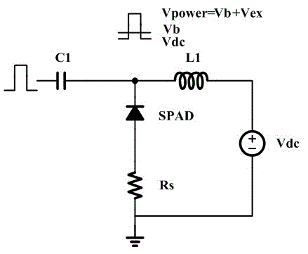
[0010] (1) Large noise: In the existing gated quenching recovery circuit, the gating signal will be coupled to the anode of the detector through the parasitic capacitance of the detector SPAD, resulting in noise
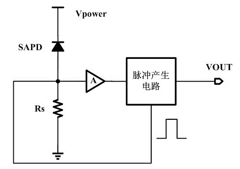
[0011] (2) Low reliability: the existing active quenching circuit can accurately control the quenching time of the detector, but the photon arrival time is not clear, and the working time of the detector cannot be controlled. If no photon arrives, the detector will be in operation for a long time state, the detector is in danger of breakdown, it is very easy to damage the detector, and the shutdown time of the active quenching circuit is short, the probability of miscounting is very high
[0012] (3) Low precision: Most of the existing technologies are composed of discrete devices, and their parasitic effects are serious, which will greatly affect the measurement accuracy
[0013] (4) Large power consumption and large area: the existing gated quenching recovery circuit requires large power consumption devices such as large inductors and large capacitors, and these devices are too large to be used in pixel arrays

Method used


Image

  • Integrated gating active quenching/restoring circuit
  • Integrated gating active quenching/restoring circuit
  • Integrated gating active quenching/restoring circuit

Examples


Embodiment Construction

[0033] The present invention will be further described below in conjunction with the accompanying drawings and embodiments.

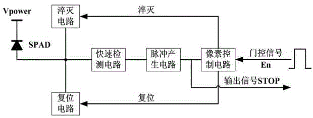
[0034] Such as image 3 As shown, the present invention comprises: fast detection circuit, pulse generating circuit, pixel control circuit, quenching and reset circuit, the negative electrode of SPAD connects high-voltage bias power supply Vpower, and fast detection circuit processes the detected SPAD anode current signal into a pulse signal , output to the pixel control circuit through the pulse generation circuit, and generate the output signal STOP for the application of the lower circuit at the same time. The output of the reset and quenching circuit is fed back to the anode of the SPAD to control the reset and quenching of the SPAD.

[0035] The integrated gated active quenching recovery circuit proposed by the present invention is as follows: Figure 4As shown, the fast detection circuit is composed of a detection resistor and an amplitude detec...


PUM


Abstract

The invention discloses an integrated gating active quenching / restoring circuit. The integrated gating active quenching / restoring circuit comprises a quick detection circuit, a pulse generation circuit, a pixel control circuit, a quenching circuit and a restoring circuit, wherein the quick detection circuit is used for processing a detected anode current signal of an SPAD (Single Photon Avalanche Diode) into a pulse signal, the pulse signal can be output through the pulse generation circuit, the pixel control circuit is controlled by an output signal and a gating signal of the pulse generation circuit, the restoring circuit and the quenching circuit are respectively controlled by outputs of the pixel generation circuit, outputs of the restoring circuit and the quenching circuit can be fed back to an anode of the SPAD, and the restoring and the quenching of the SPAD can be controlled. According to the integrated gating active quenching / restoring circuit disclosed by the invention, by adopting a gating control method, the dark counting rate of the SPAD can be effectively reduced, the quenching time can be controlled by the pulse generation circuit, and the integrated gating active quenching / restoring circuit has the advantages of compact area and low power consumption.

Description

technical field [0001] The invention relates to an integrated single-photon high-speed and high-sensitivity detection circuit for photon time-of-flight measurement in the technical field of single-photon detection. Background technique [0002] Single photon detection is a new detection technology developed in recent years. It can be used in biochip detection, medical diagnosis, non-destructive material analysis, astronomical observation, national defense and military, spectral measurement, quantum electronics and other fields, and plays an important role in it. The important engineering value of single photon detectors in some emerging high-tech fields has been more and more fully reflected. [0003] The single photon detector based on the semiconductor avalanche photodiode (APD) has the advantages of high quantum efficiency, low power consumption, all solid state, small size, low operating voltage, and insensitivity to magnetic fields, etc., and is currently the most wide...

Claims


Application Information

Patent Timeline
Patent Type & Authority Applications(China)
IPC IPC(8): G01J11/00
CPCH04N25/773
Inventor 蒋利群高新江孙力军江永清
Owner THE 44TH INST OF CHINA ELECTRONICS TECH GROUP CORP
Learn More