Hot-redundancy CAN (Controller Area Network)-bus high-fault-tolerance control terminal and method based on dual DSPs (Digital Signal Processors)
A CAN bus, control terminal technology, applied in the field of automation control, can solve the problems of imperfect fault tolerance mechanism, control failure, data loss, etc., achieve strong error correction ability and versatility, improve reliability, and achieve the effect of productization
- Summary
- Abstract
- Description
- Claims
- Application Information
AI Technical Summary
Problems solved by technology
Method used
Image
Examples
specific Embodiment approach 1
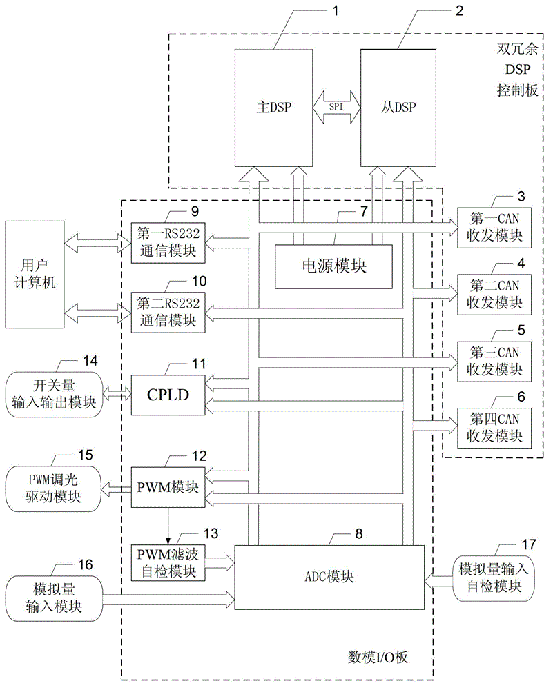
[0036] Specific implementation mode one: the following combination figure 1 Illustrate this embodiment, the hot redundant CAN bus high fault-tolerant control terminal based on double DSP described in this embodiment, it comprises digital-analog I / O board and double redundant DSP control board,
[0037] The dual redundant DSP control board includes a master DSP1, a slave DSP2, a first CAN transceiver module 3, a second CAN transceiver module 4, a third CAN transceiver module 5 and a fourth CAN transceiver module 6,
[0038] The digital-analog I / O board includes a power supply module 7, an ADC module 8, a first RS232 communication module 9, a second RS232 communication module 10, a CPLD11, a PWM module 12 and a PWM filter self-test module 13,
[0039] Communication between master DSP1 and slave DSP2 via SPI serial bus,
[0040] The main power supply circuit and the slave power supply circuit of the power supply module 7 are redundant backup structures, and the power supply modu...
specific Embodiment approach 2
[0061] Embodiment 2: This embodiment will further describe Embodiment 1. It also includes a switch input and output module 14, and the input and output terminals of the switch input and output module 14 are connected to the input and output terminals of the CPLD11.
specific Embodiment approach 3
[0062] Embodiment 3: This embodiment further describes Embodiment 1 or 2. It also includes a PWM dimming driving module 15 , and the input end of the PWM dimming driving module 15 is connected to the output end of the PWM module 12 .
PUM
 Abstract
Description
Claims
Application Information
 - R&D
- Intellectual Property
- Life Sciences
- Materials
- Tech Scout
- Unparalleled Data Quality
- Higher Quality Content
- 60% Fewer Hallucinations
Browse by: Latest US Patents, China's latest patents, Technical Efficacy Thesaurus, Application Domain, Technology Topic, Popular Technical Reports.
© 2025 PatSnap. All rights reserved.Legal|Privacy policy|Modern Slavery Act Transparency Statement|Sitemap|About US| Contact US: help@patsnap.com


