High-power DC voltage converter

A boost converter and power electronics technology, which is applied in the direction of high-efficiency power electronic conversion, DC power input conversion to DC power output, output power conversion device, etc., can solve relatively expensive problems and achieve the effect of reducing power loss

Inactive Publication Date: 2013-06-12
HEIDELBERGER DRUCKMASCHINEN AG
View PDF8 Cites 2 Cited by
  • Summary
  • Abstract
  • Description
  • Claims
  • Application Information

AI Technical Summary

Problems solved by technology

The switching circuit described in this application includes multip...

Method used


Image

  • High-power DC voltage converter
  • High-power DC voltage converter
  • High-power DC voltage converter

Examples


Embodiment Construction

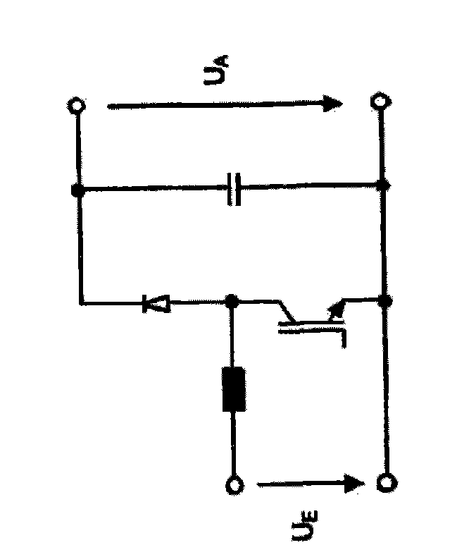
[0021] exist figure 1 The boost converter switching circuit is shown in , which operates from a relatively low input voltage U E generate a higher output voltage U A . The boost converter switching circuit basically consists of an inductor in the form of a coil, a diode and an energy storage capacitor. The inductance can be temporarily grounded by means of bipolar transistors, MOSFETs or IGBTs. When the switch is open, the inductor tries to maintain the current flow. The voltage thus rises until it exceeds the output voltage U across the capacitor A and the diode conducts. Thereafter at a first instant the current flows unchanged and charges the capacitor. At this point the magnetic field of the inductor weakens, transferring its energy to the capacitor and possibly a downstream load. The problem with this type of circuit is that the transistor has to be turned on under load, which causes corresponding switching losses.

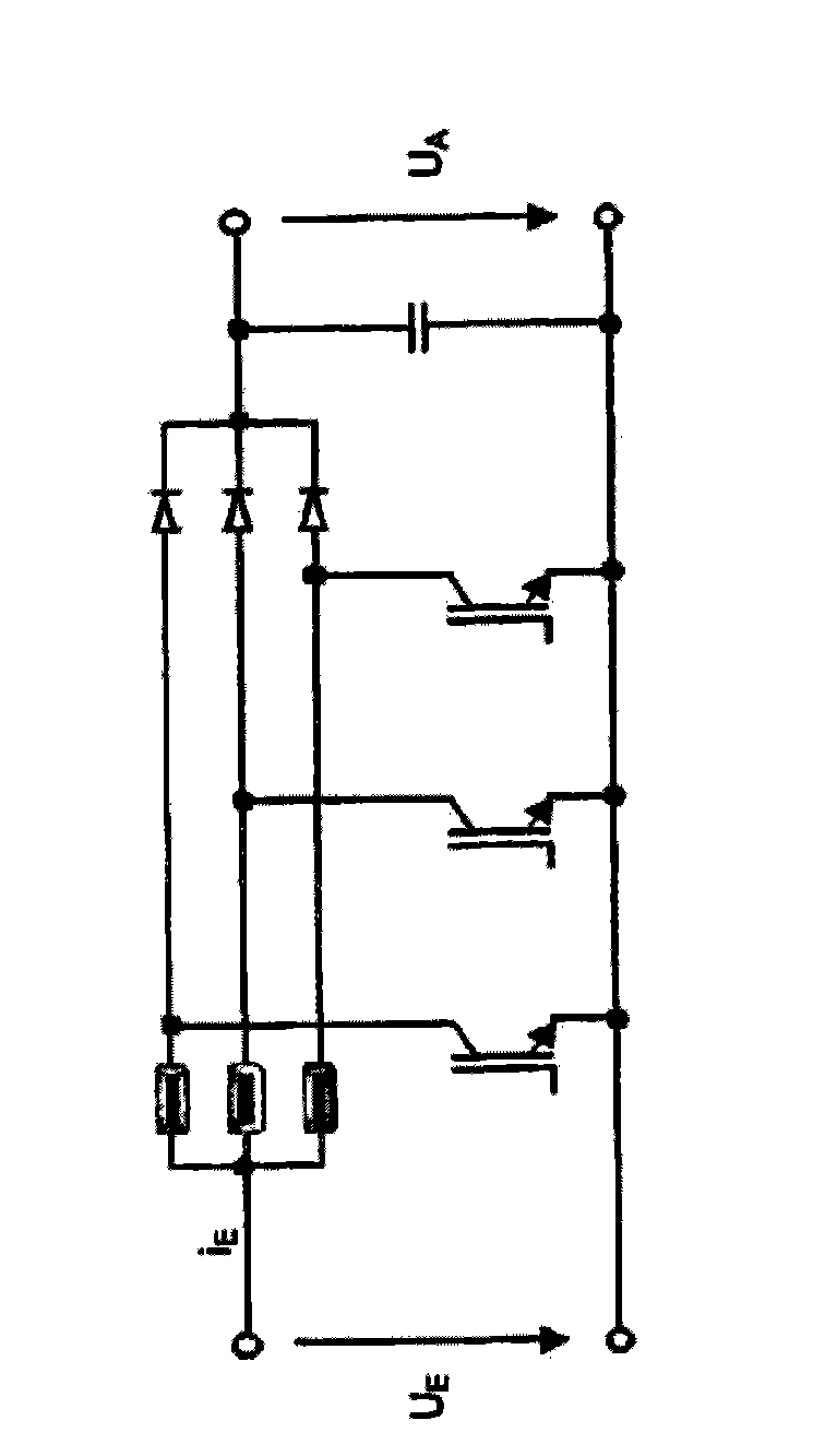
[0022] figure 2 shown with figure 1 power el...


PUM


Abstract

The invention relates to an electrical switch device comprising a boost converter switch circuit. The boost converter switch circuit includes an inductor and a first switch (T1), and is used for generating an output voltage (UA) that is higher than an input voltage (UE). The electrical switch device is characterized by being equipped with a second switch (T2) which is used for guiding the inductor in the boost converter switch circuit to genrate currents (iE, iL) when the first switch (T1) is turned off.

Description

technical field [0001] The invention relates to an electrical switching device having a boost converter switching circuit with an inductor and a first switch for generating an output voltage higher than an input voltage. Background technique [0002] Such electrical switching devices are used to step up the low voltage, eg, variable battery voltage of about 200V, to the standard motor voltage of 500V usable by three-phase AC drive motors in electric vehicles. Such a boost converter switching circuit for supplying current to an electric vehicle is disclosed in the German translation of the patent application DE11 2005 003041 T5. Here a boost converter is used, which can also act as a buck converter, transferring current not only from the battery to the motor, but also in reverse. A switching circuit combining a boost-and-buck converter basically consists of an inductor and two transistors with parallel diodes. Whether the switching circuit works as a boost converter or as a...

Claims


Application Information

Patent Timeline
IPC IPC(8): H02M3/158
CPCH02M3/1584H02M1/0032H02M3/1586Y02B70/10
Inventor K-D·克莱伯奥姆许特V·埃塞尔J·孔茨J·赖特尔K·阿尔布雷希特J·贝希特勒J·埃克M·克吕格尔H·迈耶J·舒讷
Owner HEIDELBERGER DRUCKMASCHINEN AG
Why Eureka
Try Eureka