Luminescent material, and organic light-emitting element, wavelength-converting light-emitting element, light-converting light-emitting element, organic laser diode light-emitting element, dye laser, display device, and illumination device using same
A technology of organic light-emitting elements and light-emitting materials, which can be used in light-emitting materials, lighting devices, lasers, etc., and can solve problems such as short life and poor light resistance
- Summary
- Abstract
- Description
- Claims
- Application Information
AI Technical Summary
Problems solved by technology
Method used
Image
Examples
no. 1 approach
[0075]
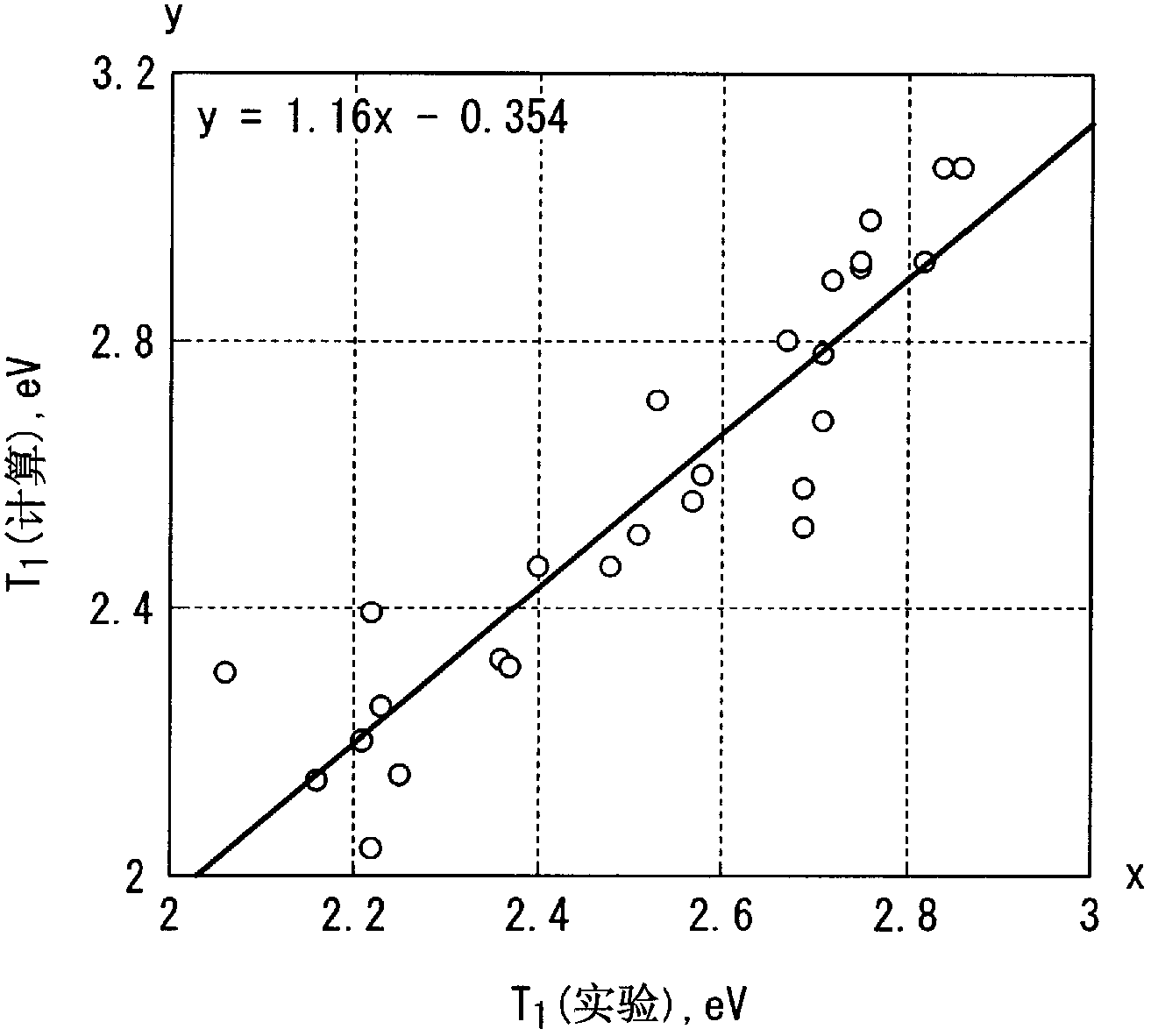
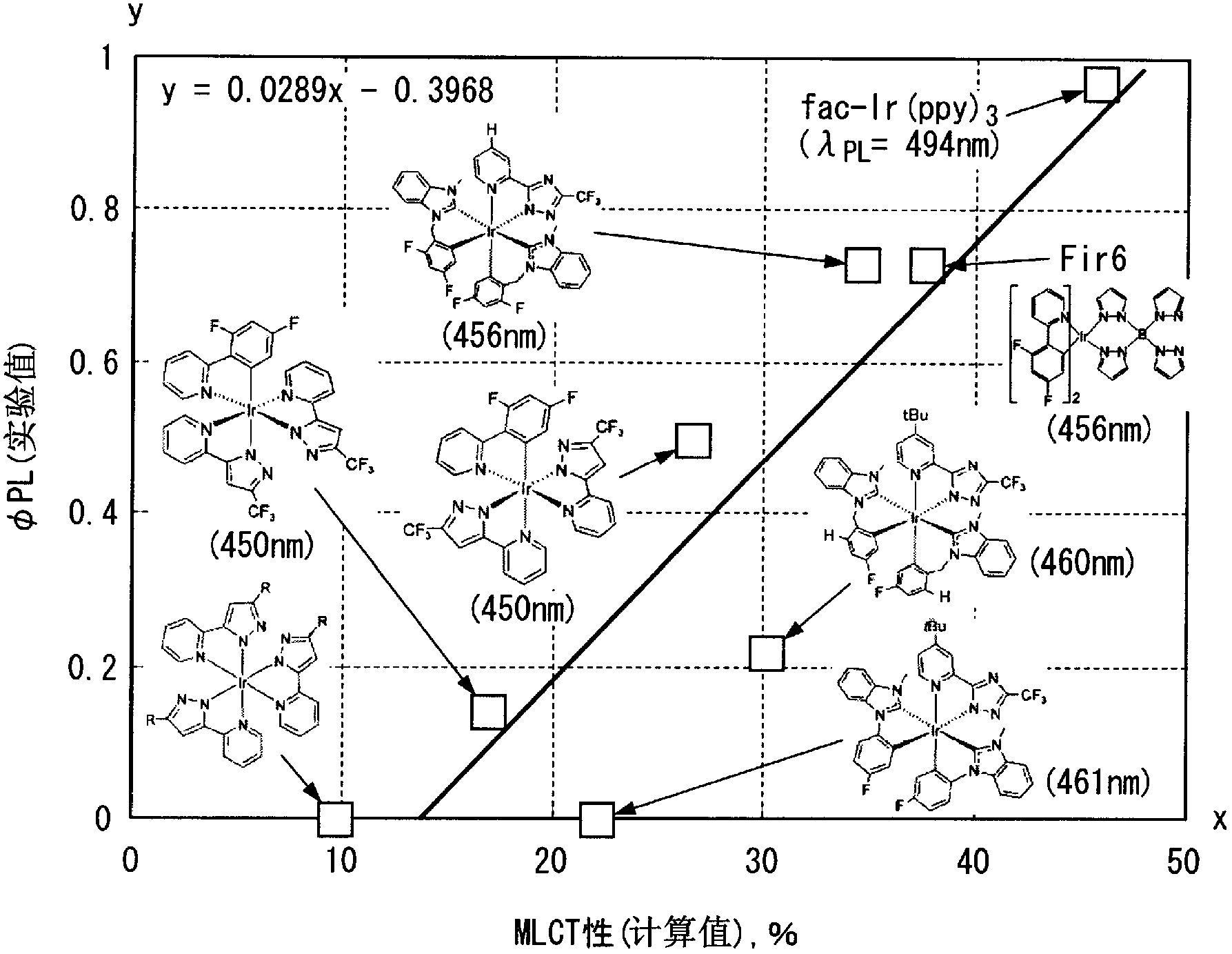
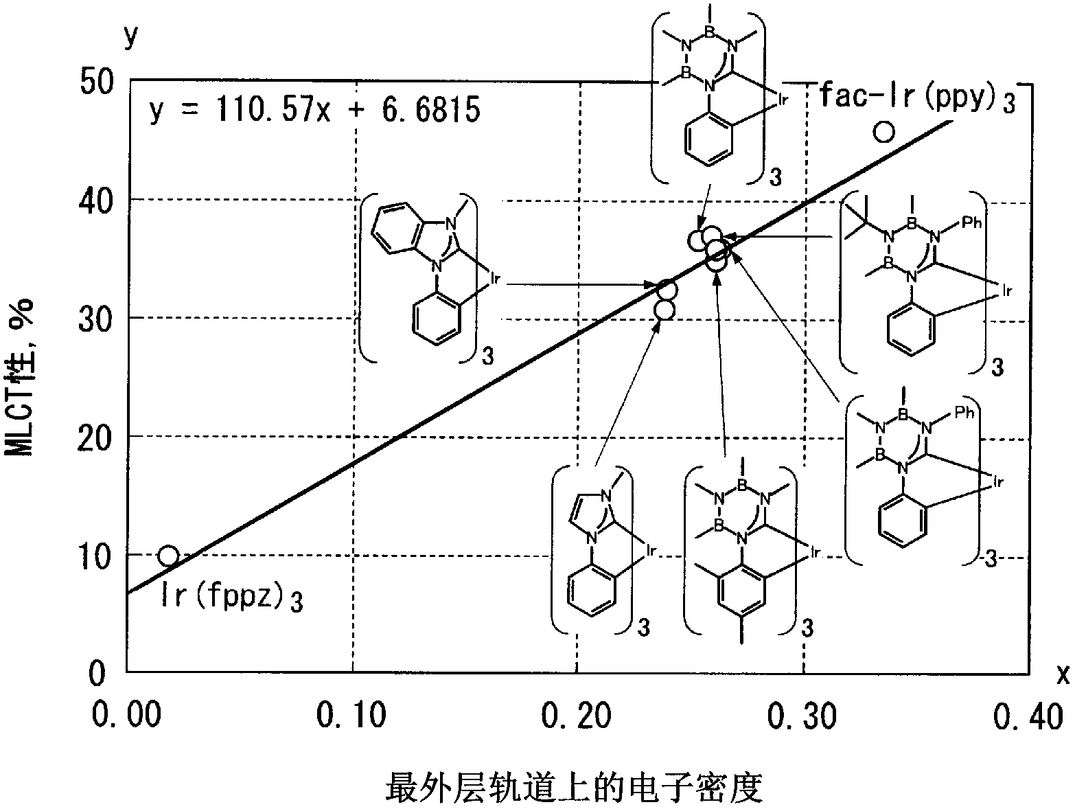
[0076] As a result of painstaking research by the present inventors, it was found that transition metal complexes can emit blue phosphorescence with good efficiency, and the above transition metal complexes have at least one A ligand whose electron density is greater than 0.239 and less than 0.711 in the outermost p-orbital of the highest occupied orbital (HOMO) energy level of the element that coordinates with the metal. In addition, in the quantum chemical calculation in this embodiment, the quantum chemical calculation Gaussian09 program (Gaussian09Revision-A.02-SMP) using the density functional calculation method (DFT method) is used to apply the basis function 6- 31G, in the case of metal complexes, apply the basis function LanL2DZ for Ir complexes and 6-31G* except for Ir. In addition, information on quantum chemical calculations (Gaussian09 / DFT / RB3LYP / 6-31G) can be obtained from, for example, http: / / www.gaussian.com / index.htm (acknowledged September 8, 2011)....
no. 2 approach
[0236] Figure 7 It is a schematic cross-sectional view showing a second embodiment of the organic light-emitting element of this embodiment. Figure 7 The illustrated organic light emitting element 20 has a substrate 1 , a TFT (Thin Film Transistor) circuit 2 provided on the substrate 1 , and an organic light emitting element 10 (hereinafter, sometimes referred to as “organic EL element 10 ”). The organic light emitting element 10 has: a pair of electrodes 12 and 16 provided on the substrate 1 ; and an organic EL layer (organic layer) 17 sandwiched between the pair of electrodes 12 and 16 . The organic light emitting element 20 is a top emission type organic light emitting element driven by an active driving method. In addition, in Figure 7 in, for with Figure 6 The same constituent elements of the illustrated organic light emitting element 10 are given the same reference numerals, and description thereof will be omitted.
[0237] Figure 7 The illustrated organic ligh...
Embodiment
[0351] Hereinafter, the present invention will be described in more detail based on examples, but the present invention is not limited by the following examples.
[0352] [Synthesis of transition metal complexes]
[0353] The compounds synthesized in Synthesis Examples 1 to 8 are shown below. In addition, in the following structural formulas, Ph represents a phenyl group. In addition, in the following synthesis examples, the compounds at each stage and the final compound (transition metal complex) were identified by MS spectroscopy (FAB-MS).
[0354]
PUM
| Property | Measurement | Unit |
|---|---|---|
| thickness | aaaaa | aaaaa |
| particle size | aaaaa | aaaaa |
| particle size | aaaaa | aaaaa |
Abstract
Description
Claims
Application Information
 - R&D
- Intellectual Property
- Life Sciences
- Materials
- Tech Scout
- Unparalleled Data Quality
- Higher Quality Content
- 60% Fewer Hallucinations
Browse by: Latest US Patents, China's latest patents, Technical Efficacy Thesaurus, Application Domain, Technology Topic, Popular Technical Reports.
© 2025 PatSnap. All rights reserved.Legal|Privacy policy|Modern Slavery Act Transparency Statement|Sitemap|About US| Contact US: help@patsnap.com


