
Guide dust-eliminating device for drill hole

A guiding and dust-proof technology, applied to drill pipes, drill pipes, drilling equipment, etc., can solve problems such as environmental pollution, drill sticking, and potential safety hazards, and achieve the effects of avoiding damage, reducing maintenance costs, and maintaining stability

Inactive Publication Date: 2013-06-19
SHANDONG SPRING DRILL
View PDF5 Cites 9 Cited by
  • Summary
  • Abstract
  • Description
  • Claims
  • Application Information

AI Technical Summary

Problems solved by technology

[0002] At present, when drilling in mining areas, wind power is usually used to remove the dust in the drilling hole, causing the dust in the drilling hole to be discharged directly, causing serious pollution and bringing serious harm to the physical and mental health of the operators, and there are also major safety hazards , dust must be eliminated. The traditional method of dust elimination is usually to set a circular spray at the drilling construction site, and to set a large spray on the return air side 10m away from the construction site. Dust removal
Especially for coal mining areas, some coal is brittle and hard on the excavation surface. When the drill bit cuts the coal wall, the coal powder particles produced are fine and large in quantity. The coal dust content in the air on the return air side of the construction site greatly exceeds the specified value, which seriously pollutes the environment and poses a major safety hazard
If hydraulic impact drilling is used for powder discharge, the combination of water and powder will easily cause drill sticking, which will affect the drilling efficiency of the drill pipe.

Method used


Image

  • Guide dust-eliminating device for drill hole

Examples


specific Embodiment approach

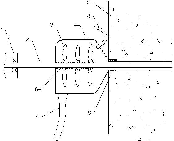
[0015] Specific embodiments: a drilling-guided dust removal device, comprising a dustproof outer cover 4 and a drill pipe 2, the drill pipe 2 penetrates the dustproof outer cover 4 in the axial direction, and a water spray head 8 is arranged inside the dustproof outer cover 4. The center of the dust cover 4 is slidingly socketed with the drill pipe 2 through the sliding sleeve 6; the sliding sleeve 6 is equipped with a multi-layer freely rotatable fan ring 3 through bearings; the supporting rotating bearings of the fan ring 3 are fixed together , the fan circles of each layer rotate synchronously. The bottom of the dust-proof outer cover 4 is provided with a slurry outlet 7, and the front end of the dust-proof outer cover 4 is funnel-shaped and is sealed and connected with the drilled hole. One end of the sliding sleeve 6 is fixedly connected with the rear end surface of the dustproof cover 4 . The dust-proof outer cover 4 is provided with an annular shaft sleeve 9 which can ...


PUM


Abstract

The invention relates to environment-friendly equipment for a mine, particularly provides a dust-eliminating device used for controlling dust, and particularly relates to a guide dust-eliminating device for a drill hole. The device comprises a dustproof outer shell and a drill rod, wherein the drill rod penetrates through the dustproof outer shell along the axial direction, a water sprayer is arranged in the dustproof outer shell, and the center of the dustproof outer shell is connected with the drill rod in a sliding and sleeved mode through a sliding sleeve. A plurality of layers of fan rings capable of freely rotating are arranged on the sliding sleeve through bearings, the lower portion of the dustproof outer shell is provided with a slurry outlet, and the front end face of the dustproof outer shell is in a funnel shape and is connected with the drill hole in a sealing mode. Therefore, the dustproof outer shell can slide along the drill rod, the front end of the dustproof outer shell can be inserted into the drill hole and fixed, and a guide function is achieved on the drill rod. The device is dual-purpose, has a dustproof function and the guide function for the drill rod, prevents drill rod slip damage caused by shaking and collision of the drill rod from occurring, reduces maintenance cost, and is beneficial for development of enterprises.

Description

technical field [0001] The invention relates to mining environmental protection equipment, in particular to dust control equipment for dust control, in particular to a drilling-guided dust control device. Background technique [0002] At present, when drilling in mining areas, wind power is usually used to remove the dust in the drilling hole, causing the dust in the drilling hole to be discharged directly, causing serious pollution and bringing serious harm to the physical and mental health of the operators, and there are also major safety hazards , dust must be eliminated. The traditional method of dust elimination is usually to set a circular spray at the drilling construction site, and to set a large spray on the return air side 10m away from the construction site. Dust. Especially for coal mining areas, some coal is brittle and hard on the excavation surface. When the drill bit cuts the coal wall, the coal powder particles produced are fine and large in quantity. This...

Claims


Application Information

Patent Timeline
Patent Type & Authority Applications(China)
IPC IPC(8): E21B21/015E21B19/24
Inventor 于洪涛王海妹
Owner SHANDONG SPRING DRILL
Learn More