Method for manufacturing chromium sidewall attenuation type phase-shifting mask used in extreme ultra-violet lithography

A technology of extreme ultraviolet lithography and phase shift mask, which is applied in the field of making chromium sidewall attenuation type phase shift mask for extreme ultraviolet lithography, and can solve the problems of complex manufacturing, lower resolution, lower contrast of exposure results, etc.

Inactive Publication Date: 2013-06-19
INST OF MICROELECTRONICS CHINESE ACAD OF SCI
View PDF3 Cites 10 Cited by
  • Summary
  • Abstract
  • Description
  • Claims
  • Application Information

AI Technical Summary

Problems solved by technology

[0004] The reflective alternating phase shift mask in the reflective phase shift mask was first proposed, and its improvement on optical exposure is also the most significant, but the reflective alternate phase shift mask has three main disadvantages: 1. This form of masking is only suitable for highly periodic patterns
3. Complex manufacturing
[0006] However, when the reflective attenuation phase-shift mask is working, the incident wave is obliquely incident, which will form exposure shadow areas and diffraction effects in the phase-shift area, resulting in a decrease in the contrast of the exposure results and the resolution.

Method used


Image

  • Method for manufacturing chromium sidewall attenuation type phase-shifting mask used in extreme ultra-violet lithography
  • Method for manufacturing chromium sidewall attenuation type phase-shifting mask used in extreme ultra-violet lithography
  • Method for manufacturing chromium sidewall attenuation type phase-shifting mask used in extreme ultra-violet lithography

Examples


Embodiment Construction

[0017] In order to make the objectives, technical solutions, and advantages of the present invention clearer, the following further describes the present invention in detail in conjunction with specific embodiments and with reference to the accompanying drawings.

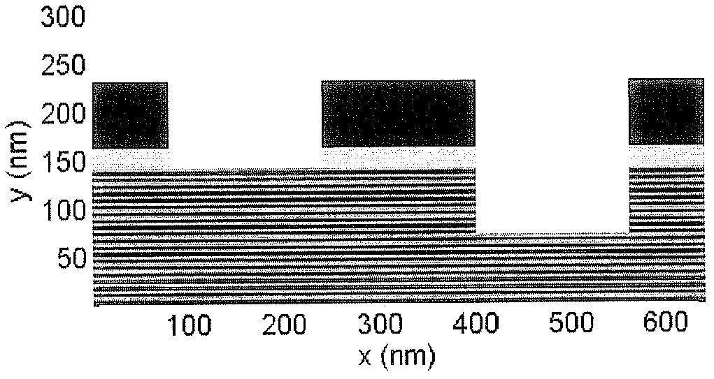
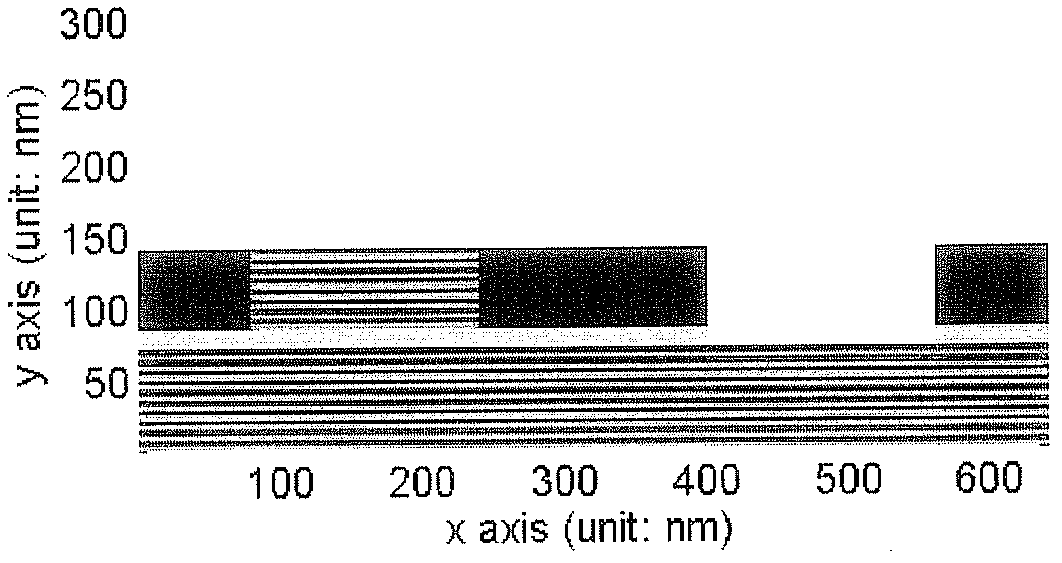
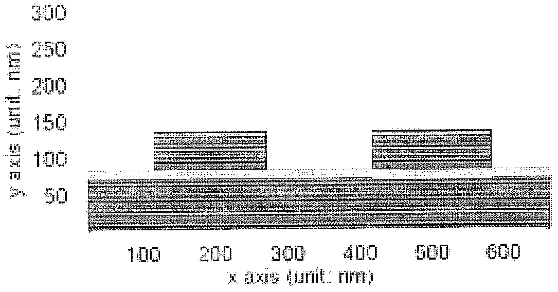
[0018] At present, the structural design of extreme ultraviolet lithography masks is mainly as follows figure 1 or figure 2 The reflective alternating phase shift mask shown, and as image 3 The two structures of the traditional reflective attenuated phase shift mask are shown. The extreme ultraviolet lithography chromium sidewall attenuation type phase shift mask provided by the present invention, such as Figure 4 Shown, with figure 1 Shows the traditional alternating phase shift mask and image 3 Compared with the shown attenuated phase-shifting mask structure, chromium sidewalls are added on both sides of the phase-shifting area of ​​the traditional attenuated mask structure, and the simulation result of the far-fie...


PUM

PropertyMeasurementUnit
thicknessaaaaaaaaaa
thicknessaaaaaaaaaa
thicknessaaaaaaaaaa

Abstract

The invention discloses a method for manufacturing a chromium sidewall attenuation type phase-shifting mask used in extreme ultra-violet lithography. Firstly, a plurality of multilayer reflectors are manufactured according to a manufacturing method for a conventional extreme ultra-violet lithography mask; then a phase-shifting layer structure is manufactured on an electron beam resist by using a micro-nano machining technology, and an absorber material chromium is deposited on a large area; and finally, the absorber material chromium is anisotropically etched, only leaving the attenuation type phase-shifting layer chromium sidewalls, so that the chromium sidewall attenuation type phase-shifting mask used in the extreme ultra-violet lithography can be obtained. The chromium sidewall attenuation type phase-shifting mask is obtained by one time of electron beam exposure, two times of magnetron sputtering deposition of multilayer reflecting layers and the phase-shifting layer, one time of atomic layer deposition of the chromium material on a large area, and one time of anisotropic etching of the chromium material. The chromium sidewall is added in two sides of the attenuation type phase-shifting mask, and the exposure shadow and the diffraction effect in the extreme ultra-violet lithography are depressed by the chromium sidewalls, so that a more efficient function of resolution enhancement than that of a conventional attenuation type phase-shifting mask is obtained.

Description

Technical field [0001] The invention relates to the technical field of nano-microprocessing in microelectronics technology, and particularly relates to a method for manufacturing a chromium sidewall attenuation type phase shift mask for extreme ultraviolet lithography. Background technique [0002] The concept of phase-shifting mask was proposed by Levenson et al. in 1982. It is the biggest innovation in optical exposure technology in the past ten years. Its basic principle is to improve imaging contrast and depth of focus by modulating the phase of incident light waves. Phase-shifting masks are classified into reflective phase-shifting masks and transmissive phase-shifting masks according to their working principles. These two types of masks are based on the phase modulation of incident light waves. The principle is different, each mask can be divided into alternating phase shift mask, attenuation phase shift mask and so on. The most obvious feature of extreme ultraviolet litho...

Claims


Application Information

Patent Timeline
Patent Type & Authority Applications(China)
IPC IPC(8): G03F1/26G03F1/28
CPCG03F1/38G03F1/24G03F1/32
Inventor 李海亮谢常青刘明史丽娜朱效立李冬梅
Owner INST OF MICROELECTRONICS CHINESE ACAD OF SCI
Why Eureka
Try Eureka