Broadband circularly-polarized radio frequency identification (RFID) reader antenna

A circularly polarized and reader technology, applied in the field of broadband circularly polarized RFID reader antennas, can solve the problems of low radiation efficiency, low gain value, and large difference in operating frequency bands, and achieve high gain, increased gain, and large impedance. The effect of bandwidth

Inactive Publication Date: 2013-06-19
UNIV OF ELECTRONICS SCI & TECH OF CHINA +1
View PDF5 Cites 18 Cited by
  • Summary
  • Abstract
  • Description
  • Claims
  • Application Information

AI Technical Summary

Problems solved by technology

However, although these technologies have improved the impedance and axial ratio bandwidth of the antenna, they are still far from the required operating frequency band.
In order to seek a larger working bandwidth, a commonly used method is to

Method used


Image

  • Broadband circularly-polarized radio frequency identification (RFID) reader antenna
  • Broadband circularly-polarized radio frequency identification (RFID) reader antenna
  • Broadband circularly-polarized radio frequency identification (RFID) reader antenna

Examples


Embodiment 1

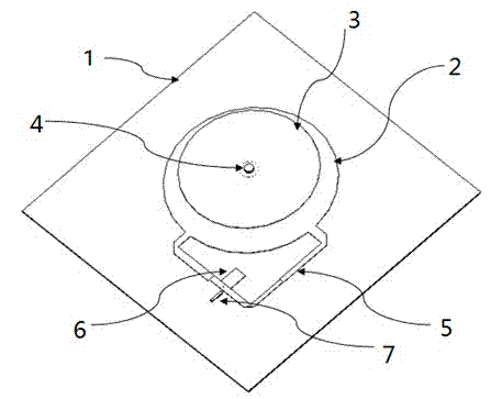
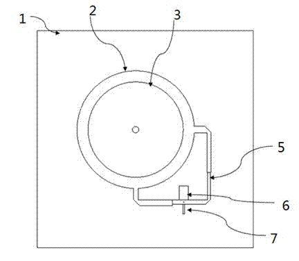
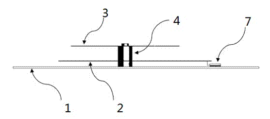
[0027] Such as Figure 1 to Figure 3 As shown, the broadband circularly polarized RFID reader antenna, the driving radiation unit adopts the driving radiation disc, the parasitic radiation unit adopts the parasitic radiation disc, the metal ground plate, the driving radiation disc and the parasitic radiation disc are all made of aluminum material, the driving radiation The radiation disk and the parasitic radiation disk form a concentric stack structure, and the center is supported by a metal support column. The distance between the driving radiation disk and the parasitic radiation disk is 20mm, and the distance between the driving radiation disk and the parasitic radiation disk can be 10mm. Choose between ~30mm. The stacked structure of the driving radiating disc and the parasitic radiating disc is placed on a rectangular metal grounding plate, and the center is supported by a metal support column. The distance between the driving radiating disc and the metal grounding plate...

Embodiment 2

[0036] Such as Figure 6 As shown, on the basis of Embodiment 1, the structure of the broadband circularly polarized RFID reader antenna is rotated along the axis, and the parts included in the antenna are the same as those of the right-handed circularly polarized antenna in Embodiment 1, except for the installation of the feeder network The position is adjusted so that the rotation direction of the electric field vector of the radiated wave generated by the antenna is left-handed along the propagation direction, and the left-handed circularly polarized wave is radiated. However, the rotation direction of the electric field vector of the radiated waves of the right-handed circularly polarized antenna in Embodiment 1 is right-handed along the propagation direction, and radiates right-handed circularly polarized waves. The working principle and performance of the antenna are the same as those of the right-handed circularly polarized antenna in Embodiment 1.

[0037] According t...


PUM

PropertyMeasurementUnit
Radiusaaaaaaaaaa
Radiusaaaaaaaaaa
Radiusaaaaaaaaaa

Abstract

The invention discloses a broadband circularly-polarized radio frequency identification (RFID) reader antenna. The broadband circularly-polarized RFID reader antenna comprises a metal grounding plate, a driving radiation unit, a spurious radiation unit, a feed coaxial line, a metal support pillar and a feed network, wherein the driving radiation unit, the spurious radiation unit and the metal grounding plate have a cascade structure; the metal support pillar is fixedly arranged on the metal grounding plate; the spurious radiation unit and the driving radiation unit are fixedly arranged on the metal support pillar sequentially; and the feed coaxial line and the feed network are electrically connected with the driving radiation unit. According to the broadband circularly-polarized RFID reader antenna, the driving radiation unit is excited by the feed network, and the spurious radiation unit is subjected to coupled feeding by the driving radiation unit; operating modes of the two radiation units are the same, and two resonant frequencies are approximate, so that double-humped resonance is formed, and the work bandwidth of the antenna is increased; and the spurious radiation unit achieves an effect of a director to increase the gain of the antenna, so that the aim of providing an electromagnetic wave with high gain, large impedance bandwidth, large axial ratio bandwidth and large axial ratio beamwidth is fulfilled.

Description

technical field [0001] The invention relates to the field of electromagnetic antennas, in particular to a broadband circularly polarized RFID reader antenna. Background technique [0002] Radio Frequency Identification (RFID for short) is an automatic identification technology that began to emerge in the 1990s. It uses radio frequency signals to achieve contactless information transmission through spatial coupling (alternating magnetic fields or electromagnetic fields) and through The technology by which the information transmitted achieves the purpose of identification. Radio frequency identification (RFID) technology is now more and more widely used, especially in the ultra high frequency (UHF) frequency band, which has great potential for development. However, each country has its own UHF RFID operating frequency bands, for example, China's operating frequency bands are 840.5-844.5 MHz and 920.5-924.5MHz; Europe is 866-869MHz, South America and North America are 902-928M...

Claims


Application Information

Patent Timeline
IPC IPC(8): H01Q21/24H01Q1/22
Inventor 文光俊张庆王平
Owner UNIV OF ELECTRONICS SCI & TECH OF CHINA
Why Eureka
Try Eureka