
Single-mandril spoke type superconduction accelerating cavity and manufacture method thereof

A technology of superconducting accelerating cavity and manufacturing method, which is applied in the direction of manufacturing tools, linear accelerators, metal processing equipment, etc., and can solve the problems of limiting the application prospect of single core rod and spoke type superconducting cavity, unstable operation of accelerator, strong X-ray radiation, etc. problem, to achieve the effect of simplifying the number of electron beam welding, reducing the strength and reducing the difficulty

Inactive Publication Date: 2013-06-19
PEKING UNIV
View PDF3 Cites 9 Cited by
  • Summary
  • Abstract
  • Description
  • Claims
  • Application Information

AI Technical Summary

Problems solved by technology

The secondary electron multiplication effect will consume a large amount of microwave energy, increase the load on the superconducting cavity, and generate strong X-ray radiation, resulting in unstable operation of the accelerator
This problem will limit the application prospect of single mandrel and spoke superconducting cavities

Method used


Image

  • Single-mandril spoke type superconduction accelerating cavity and manufacture method thereof
  • Single-mandril spoke type superconduction accelerating cavity and manufacture method thereof
  • Single-mandril spoke type superconduction accelerating cavity and manufacture method thereof

Examples


Embodiment Construction

[0019] The present invention will be described in detail below in conjunction with the accompanying drawings and embodiments.

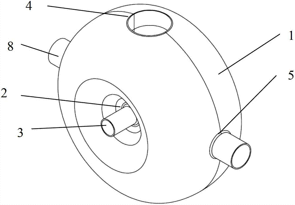
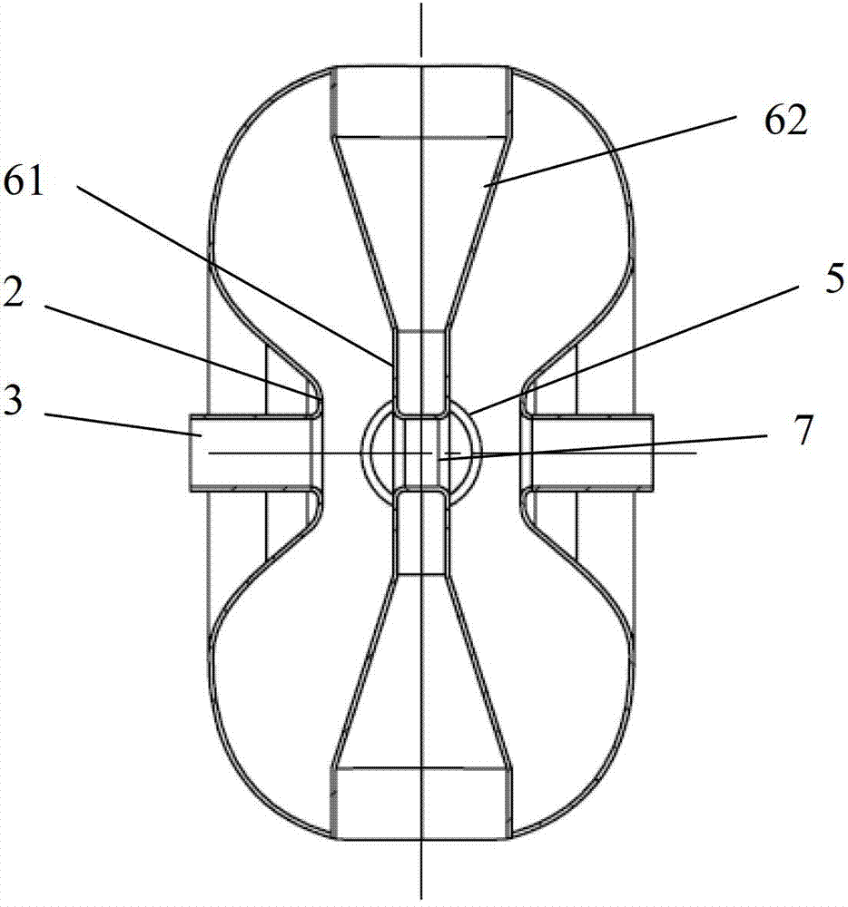
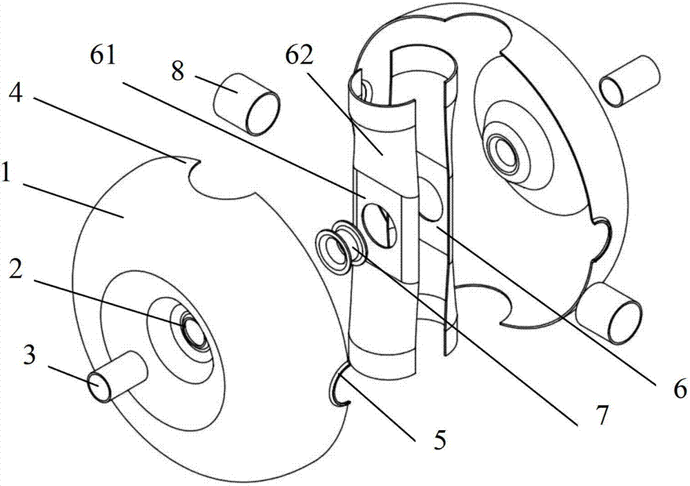
[0020] like Figure 1 ~ Figure 3 As shown, the device of the present invention includes a cavity 1, which is welded by two half-cavities 1 with exactly the same shape. A pair of bundle tube holes 2 are arranged symmetrically in the central recess of the cavity 1, a bundle of tubes 3 are respectively welded in the two bundles of tube holes 2, and a flange (not shown in the figure) is welded on the outside of the two bundles of tubes 3 respectively. The flange can be connected with external devices. A pair of mandrel holes 4 are symmetrically arranged on the cavity perpendicular to the connecting direction of the two bundles of tubes 3 , and a pair of cleaning holes 5 are symmetrically arranged on the cavity 1 separated from the two mandrel holes 4 by 90°. In the two mandrel holes 4, there is a mandrel 6 welded by two halves of the thin-walled cavity....


PUM


Abstract

The invention relates to a single-mandril spoke type superconduction accelerating cavity and a manufacture method thereof, wherein an optimal beta range is 0.1-0.1. The single-mandril spoke type superconduction accelerating cavity comprises a cavity body. The cavity body is formed by two semi-cavity bodies with the same shape in a welding mode. The outline of the cavity body is in an ellipsoid shape. A pair of beam tube holes is symmetrically formed in the center of the cavity body. A beam tuber is welded in each of the two beam tube holes. A flange is welded on the outer side of each of the two beam tubes. A pair of mandril holes is symmetrically formed in the cavity body and is perpendicular to the direction of the connecting line of the two beam tubes. A pair of cleaning holes is symmetrically formed in the cavity body and is 90 degrees away from the two mandril holes. A mandril which is formed by two half thin-wall cavities in a welding mode is welded in the two mandril holes. The middle section of the mandril is in straight barrel shape, and two ends of the mandril are in a symmetrical hopper shape. The two hopper-shaped end openings are respectively welded on the corresponding mandril holes. A center beam tube penetrates through and is welded on the middle section of the mandril. The center beam tube is located on the same axis with the beam tubes at the two ends. A cleaning tube is welded in each of the two cleaning holes. A flange is welded on the outer side of each of the two cleaning tubes, and the flanges are connected with an external device. The single-mandril spoke type superconduction accelerating cavity can be well applied to an injector of an accelerator transmutation system.

Description

technical field [0001] The present invention relates to a strong current proton acceleration chamber, in particular to a single mandrel spoke type superconducting acceleration chamber which can suppress the secondary electron multiplication effect and its Manufacturing method. Background technique [0002] In recent years, the use of nuclear energy has developed rapidly in our country, and the safety of nuclear energy use and nuclear waste disposal have become the main issues that limit the development of nuclear energy in the future. As one of the solutions to the nuclear energy utilization problem, the accelerator-driven transmutation system is mainly composed of a high-current proton linear accelerator and a high-throughput target. The single-mandrel spoke-type superconducting cavity is one of the important components of the high-current proton linear accelerator (such as Figure 5 ~ Figure 7 shown), especially for the acceleration of the middle and low energy segments. ...

Claims


Application Information

Patent Timeline
IPC IPC(8): H05H9/00H05H7/20B23P15/00B23K15/06
Inventor 鲁向阳姚中元周奎杨柳杨自钦
Owner PEKING UNIV
Learn More