Macro film and fiber consisting of nanocapsules and nanotubes and preparation method thereof

A technology of nanocapsules and carbon nanotubes, which can be used in radiation absorbing coatings, ion implantation plating, coatings, etc., can solve the problem that the density cannot meet the requirements of wave absorption.

Inactive Publication Date: 2013-06-26
INST OF METAL RESEARCH - CHINESE ACAD OF SCI
View PDF4 Cites 13 Cited by
  • Summary
  • Abstract
  • Description
  • Claims
  • Application Information

AI Technical Summary

Problems solved by technology

[0007] The above-mentioned nanomaterials usually exist in the form of dispersed particles or carbon tubes. They can only be coated on the surface

Method used


Image

  • Macro film and fiber consisting of nanocapsules and nanotubes and preparation method thereof
  • Macro film and fiber consisting of nanocapsules and nanotubes and preparation method thereof
  • Macro film and fiber consisting of nanocapsules and nanotubes and preparation method thereof

Examples


Embodiment 1

[0038] Preparation of particle films and composite fibers by plasma arc discharge technology:

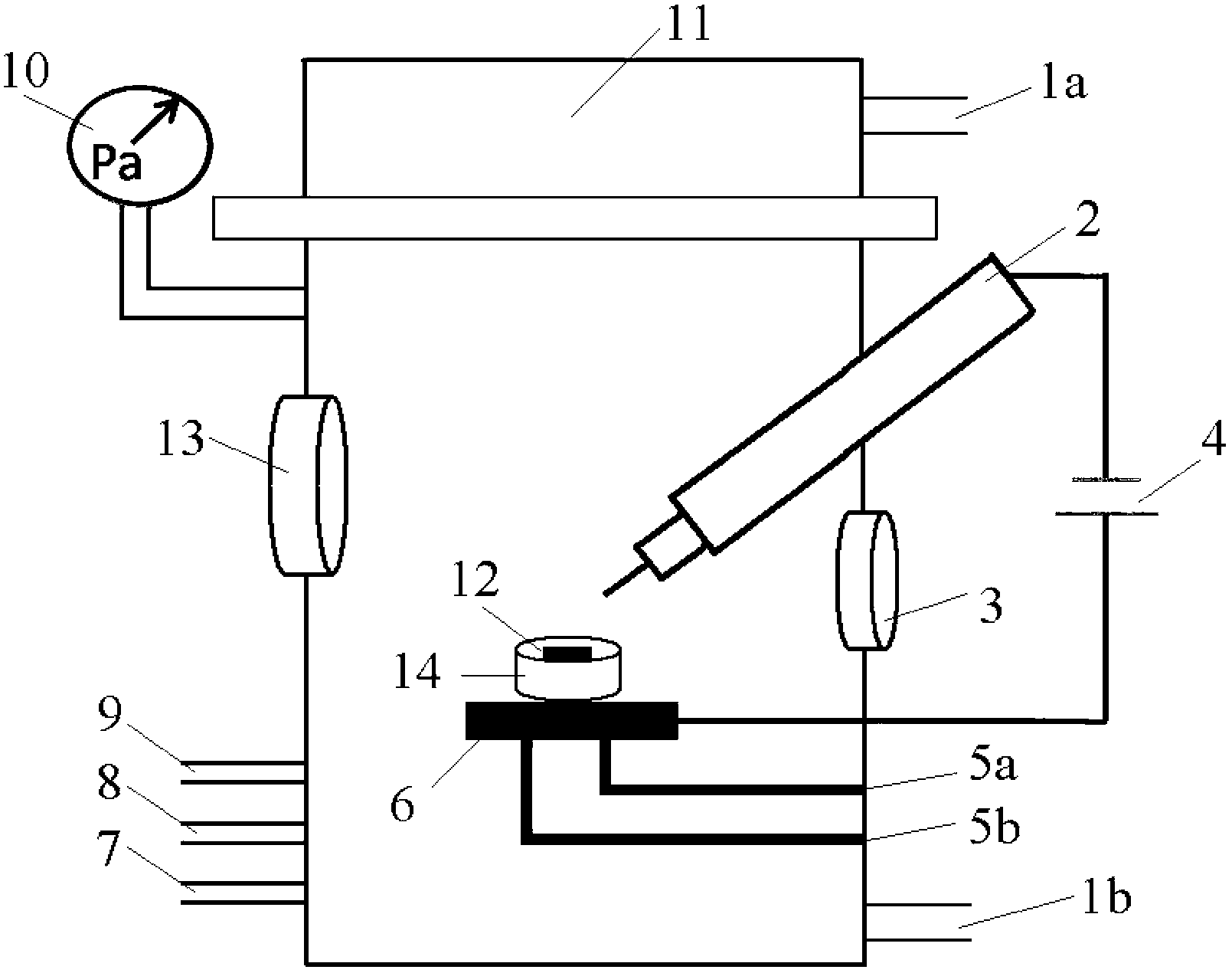
[0039] Will figure 1 The upper cover 11 of the shown device is opened, the cathode 2 used is a graphite electrode with a purity of 98%, and the consumption anode target 12 used is 10 × 10 × 10 cm 3For the iron metal block, the distance between the cathode 2 and the anode target 12 is 3 cm. Between the water-cooled copper stage 6 and the anode target 12 is a graphite crucible 14 . Cover the upper cover 11 of the device, pass cooling water, and evacuate the entire working chamber through the vacuum evacuation window 3 connected to the evacuation system, then pass argon gas and hydrogen gas through the argon gas inlet 7 and the hydrogen gas inlet 8 respectively. (Ar: 0.2Mpa, H 2 : 0.1Mpa), inject 10ml of anhydrous ethanol through the carbon supply material inlet 9 (the partial pressure of ethanol entering the cavity is 0.2Mpa), turn on the DC pulsating power supply 4, the voltage is...

Embodiment 2

[0043] Will figure 1 The upper cover 11 of the shown device is opened, the cathode 2 used is a graphite electrode with a purity of 98%, and the consumption anode target 12 used is 15×15×15cm 3 For the iron metal block, the distance between the cathode 2 and the anode target 12 is 5 mm. Between the water-cooled copper stage 6 and the anode target 12 is a graphite crucible 14 . Cover the upper cover 11 of the device, pass cooling water, and evacuate the entire working chamber through the vacuum evacuation window 3 connected to the evacuation system, then pass argon gas and hydrogen gas through the argon gas inlet 7 and the hydrogen gas inlet 8 respectively. (Ar: 0.4Mpa, H 2 : 0.2Mpa), inject 15ml of absolute ethanol through the carbon supply material inlet 9 (the partial pressure of ethanol entering the cavity is 0.28Mpa), turn on the DC pulsating power supply 4, the voltage is 10-30V, the anode target material 12 and the cathode 2 During the arc discharge, the arc discharge ...

Embodiment 3

[0045] Will figure 1 The upper cover 11 of the shown device is opened, the cathode 2 used is a graphite electrode with a purity of 98%, and the consumption anode target 12 used is 12×10×15cm 3 For the iron metal block, the distance between the cathode 2 and the anode target 12 is 8 mm. Between the water-cooled copper stage 6 and the anode target 12 is a graphite crucible 14 . Cover the upper cover 11 of the device, pass cooling water, and evacuate the entire working chamber through the vacuum evacuation window 3 connected to the evacuation system, then pass argon gas and hydrogen gas through the argon gas inlet 7 and the hydrogen gas inlet 8 respectively. (Ar: 0.5Mpa, H 2 : 0.3Mpa), inject 20ml of absolute ethanol through the carbon supply material inlet 9 (the partial pressure of ethanol entering the cavity is 0.38Mpa), turn on the DC pulsating power supply 4, the voltage is 15-40V, the anode target material 12 and the cathode 2 During the arc discharge, the arc discharge ...


PUM

PropertyMeasurementUnit
Lengthaaaaaaaaaa
Diameteraaaaaaaaaa

Abstract

The invention aims to provide a novel wave-absorbing material and a preparation method thereof. The material is formed by interweaving nanoscale Fe@C and Fe3C@C nanocapsules and carbon nano tubes, and is prepared under working gas in situ by utilizing a plasma arc discharge technology, wherein a graphite electrode serves as a cathode, pure iron serves as an anode target, and the distance of 2-30mm is reserved between the cathode and the anode; the arc discharge current is 10-400A, and the voltage is 8-40V; and the working gases are argon, hydrogen and substance capable of providing the carbon element. Because the carbon nano tube grows on the surfaces of the Fe@C and Fe3C@C nanocapsules in situ in the preparation process, and the Fe@C nanocapsules and the Fe3C@C nanocapsules are connected, so that the nanocapsules are interwoven through a self-assembling mode, and finally the granular films and fibers with the macro scale are formed. The obtained granular films and fibers are in the whole 2-18GHz frequency band and have high dielectric constant and loss factor, so that the material becomes a novel nano wave-absorbing material which can absorb electromagnetic waves in the 2-18GHz frequency band.

Description

technical field [0001] The invention belongs to the field of materials, and relates to a composite macroscopic particle film and composite fiber wave absorbing material composed of FeC nanocapsules (carbon-wrapped Fe nanocapsules), Fe3CC nanocapsules (carbon-wrapped Fe3C nanocapsules) and carbon nanotubes, and Provided is a method for preparing composite macroscopic particle film and composite fiber in a mixed atmosphere of argon, hydrogen and absolute ethanol (or methane, ethane, propane and other substances that can provide carbon elements). Background technique [0002] With the increasing use of various electrical equipment and mobile communication, these equipment also cause a large amount of electromagnetic pollution, which will have a great impact on the personal safety of the people. On the other hand, in the field of national defense and security, improving The absorption of radar electromagnetic waves by stealth aircraft, thereby improving the combat level of fight...

Claims


Application Information

Patent Timeline
IPC IPC(8): C23C14/22C23C14/06C09D5/32
Inventor 王瀚马嵩代莹莹耿殿禹刘伟张志东
Owner INST OF METAL RESEARCH - CHINESE ACAD OF SCI
Why Eureka
Try Eureka