Package support of lighting device and surface processing method thereof

A technology for encapsulating brackets and light-emitting devices, applied in electrical components, electrical solid-state devices, circuits, etc., can solve the problems affecting the long-term performance of light-emitting chip reliability, increase product defect rate, peeling, etc., to improve reliability and reliability, The effect of improving bonding strength and maintaining luminous brightness

Inactive Publication Date: 2013-06-26
SDI CORPORATION
View PDF4 Cites 3 Cited by
  • Summary
  • Abstract
  • Description
  • Claims
  • Application Information

AI Technical Summary

Problems solved by technology

[0004] However, the electroplated surface of the existing metal bracket and the reflective surface of the optical cup body are both smooth surfaces, so when the light-emitting chip is fixed on the bracket, there will be a problem of diffusion of silver glue or insulating glue, and the silver glue or insulating glue will spread in the functional area of ​​the optical cup body. When filling and encapsulating the transparent colloid, it is easy to peel off due to the different thermal expansion coefficients of the materials between the components, resulting in an increase in the defective rate of the product. Due to changes in the environment, such as changes in temperature and humidity, the thermal stress damage caused by the difference in thermal expansion coefficient between the materials and the corrosion damage of the optical module caused by the infiltration of moisture will affect the long-term performance of the reliability of the light-emitting chip, such as Prone to problems such as light decay or dead lights

Method used


Image

  • Package support of lighting device and surface processing method thereof
  • Package support of lighting device and surface processing method thereof
  • Package support of lighting device and surface processing method thereof

Examples


Embodiment Construction

[0028] In order to have a clearer understanding of the technical features, purposes and effects of the present invention, the specific implementation manners of the present invention will now be described with reference to the accompanying drawings.

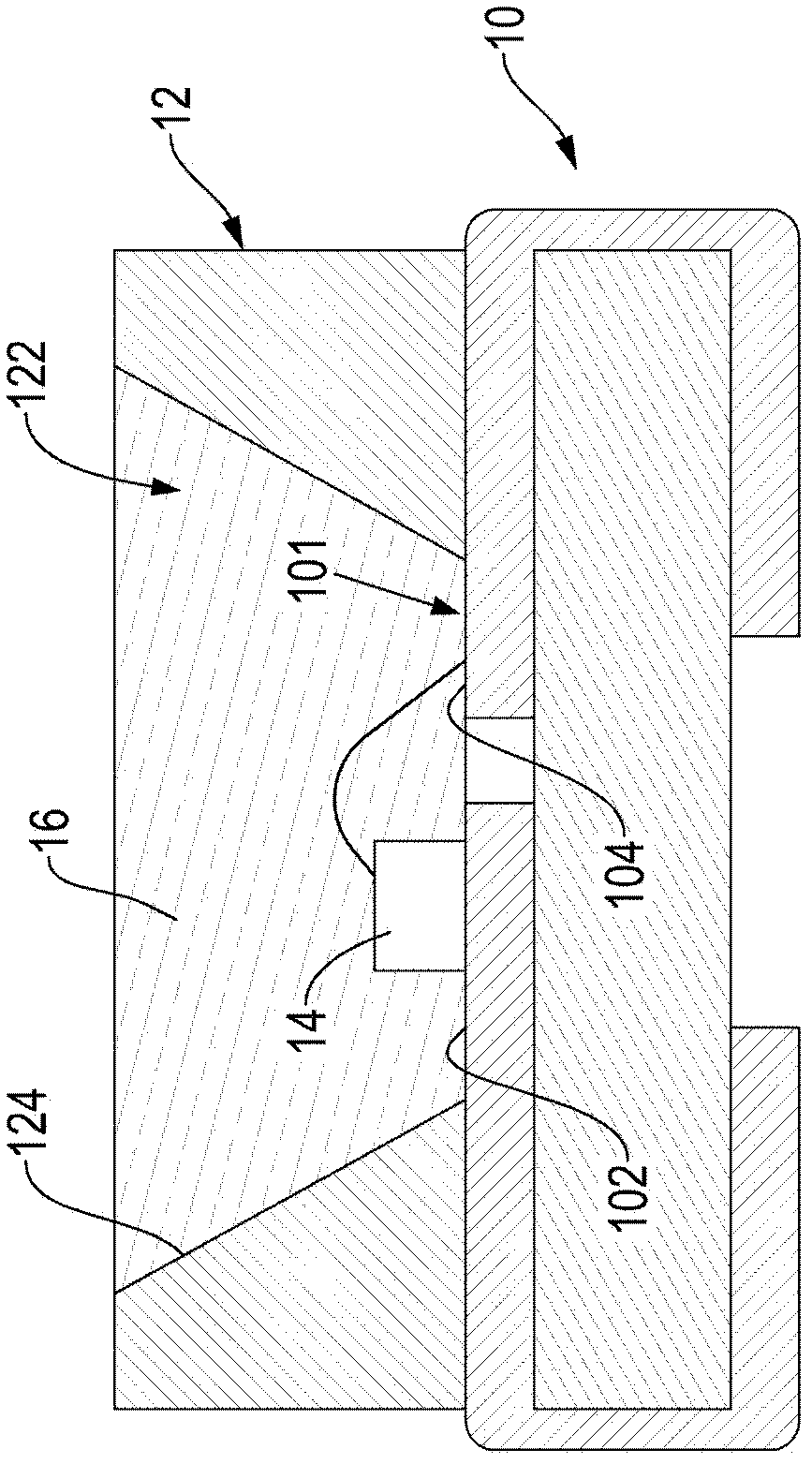
[0029] The present invention mainly provides a light-emitting device packaging bracket and its surface treatment method, please refer to figure 1 , it can be seen from the figure that the package holder structure of the present invention mainly includes a metal holder 10 and an optical cup body 12 . The metal bracket 10 can be made of copper alloy, iron alloy or aluminum alloy, preferably copper alloy. The surface of the metal bracket 10 is electroplated to form an electroplated surface, wherein the electroplating treatment can be copper-silver (Cu-Ag), nickel-silver (Ni-Ag), nickel palladium gold (NiPdAu), nickel tin (Ni-Sn), copper (Cu), nickel phosphorus (Ni-P), tin lead (Sn-Pb), nickel gold (Ni-Au), Nickel palladium gold (Ni...


PUM

PropertyMeasurementUnit
surface roughnessaaaaaaaaaa

Abstract

The invention relates to a package support of a lighting device and a surface processing method thereof. The package support comprises a metal support and a plastic light cup body arranged on the metal support. The light cup body is recessed inwards to form a function area, at least one reflection face is formed in the function area, and a wafer area is formed on the metal support corresponding to the function area of the light cup body. The wafer area of the metal support and the reflection face of the light cup body are subjected to sand blasting processing to form a rough surface respectively. The surface processing method is that the rough surface is respectively formed on the wafer area of the metal support and the reflection face of the light cup body of the package support by means of the sand blasting processing to increase combination surface area of the metal support and the light cup body and other package members and improve combination strength between the package support and other package members to achieve the aims of improving manufacture excellence rate and use credibility of the lighting device, prolonging service life and the like.

Description

technical field [0001] The invention relates to a packaging bracket of a light-emitting device and a surface treatment method thereof, in particular to a structure and a method for roughening the surface of the packaging bracket by sandblasting. Background technique [0002] The existing light-emitting device packaging bracket mainly includes a metal bracket and an optical cup body formed on the bracket. The optical cup body is concavely formed to form a functional area, and a reflective surface is formed in the functional area. The metal bracket is opposite to the optical cup. The functional area of ​​the main body forms a crystal-fixing area, and a light-emitting chip is adhered and fixed on the crystal-fixing area of ​​the bracket. Wires can be arranged between the light-emitting chip and the metal bracket to electrically connect each other, and the transparent glass is filled in the functional area of ​​the optical cup body. Light encapsulating colloid to form an encapsu...

Claims


Application Information

Patent Timeline
Patent Type & Authority Applications(China)
IPC IPC(8): H01L33/48H01L33/00B24C1/10
CPCH01L2224/48091H01L2224/48247H01L2924/00014
Inventor 刘俊杰
Owner SDI CORPORATION
Why Eureka
Try Eureka