Method for improving thermal conduction capability of printed board of surface-mounted device

A technology for surface mount devices and thermal conductivity, which is applied in the field of high heat flux density surface mount devices and electronic equipment, and can solve the problems of low thermal conductivity of thermally conductive printed boards, low heat dissipation reliability of thermal conduction paths, and high temperature of device casings. It is easy to accumulate design experience and knowledge, has reproducibility and scalability, and achieves the effect of thermal conductivity

Inactive Publication Date: 2013-06-26
10TH RES INST OF CETC
View PDF3 Cites 12 Cited by
  • Summary
  • Abstract
  • Description
  • Claims
  • Application Information

AI Technical Summary

Problems solved by technology

[0010] The purpose of the present invention is to propose a theoretically instructive method for the disadvantages of the above-mentioned existing technology, such as low heat conduction performance, long heat conduction path, and large heat conduction resistance, which lead to high device shell temperature and poor thermal reliability. 、A highly operable design and process implementation method to solve the defect of low heat dissipation reliability of the heat conduction path of surface mount devices with high heat flux density under low air pressure or vacuum conditions

Method used


Image

  • Method for improving thermal conduction capability of printed board of surface-mounted device
  • Method for improving thermal conduction capability of printed board of surface-mounted device
  • Method for improving thermal conduction capability of printed board of surface-mounted device

Examples


Embodiment Construction

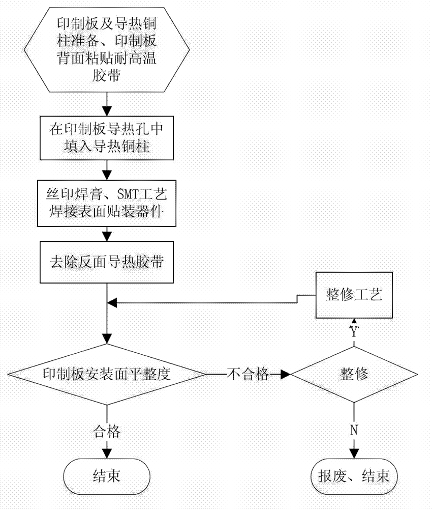
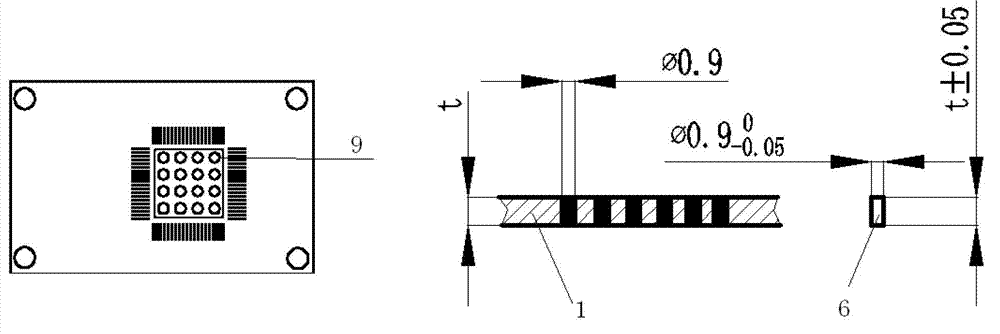
[0024] The specific implementation steps of the present invention will be further described in detail below in conjunction with the accompanying drawings.

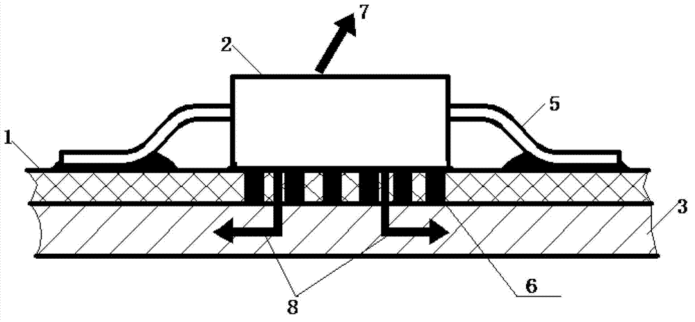
[0025] When using this method to design, the thermal conduction path should be optimized according to the assembly relationship of the device, printed board and metal box body, and the device is determined to be a surface soldered and mounted device, and its thermal conduction path is the same as figure 1 The same or a similar situation is shown for path 8 . This method can only be used when the heat dissipation characteristics of surface mount devices can be effectively improved by improving the thermal conductivity of the printed board.

[0026] refer to Figure 1 ~ Figure 3 . figure 1 It shows that the high heat flux surface mount components 2 are mounted on the bottom with metal heat dissipation bosses, and the surface mount components that can be soldered to the grounding layer of the printed board 1 through the S...


PUM


Abstract

The invention provides a method for improving thermal conduction capability of a printed board of a surface-mounted device, and aims at providing an instructive and operable method for overcoming the defects that thermal conduction printed boards in the prior art are high in working temperature, poor in thermal reliability and the like due to poor thermal conduction capability, long thermal conduction route and large thermal conduction resistance. The technical scheme includes that the method includes: determining a layout of plated-through holes and thermal conductive copper pins according to ranges of power consumption parameters of a high-thermal-flux-density surface-mounted device; establishing a replicable and extendable thermal conducting route according to assembling relations among the surface-mounted device with a metal welding surface at the bottom, the printed board and a metal box; on reverse sides of thermal conductive through holes on the printed board and the surface-mounted device, sealing thermal conductive through holes with high temperature resistant adhesive tape; and respectively pressing the thermal conductive copper pins into correspondingly thermal conductive through holes and welding. By the method for improving the thermal conduction capability of the printed board of the surface-mounted device, the defect that the thermal conduction router of the high-thermal-flux-density surface-mounted device in low air pressure or vacuum is low in reliability is solved.

Description

technical field [0001] The invention relates to a method for improving the thermal conductivity of a printed board of a surface mount device, and relates to a design and assembly process of a printed board of a surface mount device and a heat conduction copper pin, especially a surface mount device with high heat flux working under low pressure and vacuum conditions. Install electronic equipment. Background technique [0002] In spaceborne payload products, most of the packaging forms of high heat flux surface mount devices are non-airtight structures, and are in (10 -6 ~10 -7 Pa) operating in a vacuum environment, facing the requirements of long life and high reliability, thermal design is one of the very important contents in the development. Poor heat dissipation will lead to high heat flux surface mount device packaging shell temperature and poor thermal reliability. At the same time, the air often used in ground electronic equipment, various convective heat dissipatio...

Claims


Application Information

Patent Timeline
Patent Type & Authority Applications(China)
IPC IPC(8): H05K1/02H05K1/18H05K3/30H05K7/20
Inventor 方伟王勇何菊胡家渝郑国洪
Owner 10TH RES INST OF CETC
Why Eureka
Try Eureka