Vertical roller mill

A vertical roller mill and machine base technology, which is applied in the direction of electromechanical devices, casings/covers/supports, electrical components, etc., can solve the problem of aggravating the wear and damage of drive shaft bearings, large-diameter static pressure bearings, and mechanical transmission efficiency. Loss, poor stability and other problems, to achieve the effect of reducing the requirements of machining accuracy and mechanical properties, the risk of damage is small, and the positional relationship is stable

Active Publication Date: 2013-07-10
CHINA ERZHONG GRP DEYANG HEAVY IND
View PDF6 Cites 6 Cited by
  • Summary
  • Abstract
  • Description
  • Claims
  • Application Information

AI Technical Summary

Problems solved by technology

[0004] 1. Low transmission efficiency: Since this reducer is a three-stage transmission, its mechanical efficiency is about 94%, and there is about 6% loss of mechanical transmission efficiency;
[0005] 2. The manufacturing cost of the transmission system is high: due to the high processing precision requirements of the spiral bevel gear pair and the planetary gear train of the special reducer, the cost of the reducer is very high, so that the manufacturing cost of the entire transmission system is very high;
[0006] 3. The failure rate of the transmission system is high: due to the large number of components in the transmission system composed of motors, couplings, and special reducers, and because the reducer is subjected to the grinding disc, the gravity of the material and the impact load of the grinding process, it causes failures High incidence;
[0007] 4. Inconvenient maintenance of the transmission system: Since the reducer is a closed structure, when the reducer breaks down, the millstone must be lifted up, and then the reducer must be pulled out for maintenance, which makes the disassembly and assembly of the reducer expensive and time-consuming
[0009] However, during the operation of the vertical roller mill, due to the hard connection between the transmission shaft and the grinding disc, the load generated during the operation, especially the radial component of the impact load, will form a bending moment on the transmission shaft, which will lead to During the process, the vibration is large, the stability is poor, the grinding effect is poor, and the wear and damage of the drive shaft bearing and the large-diameter static pressure bearing are aggravated. When the impact is large, the drive shaft may even be damaged, so the use effect is poor.
Secondly, the maintenance of the transmission shaft and its bearings requires a complete disassembly of the whole machine, so there are many procedures, time-consuming, inconvenient maintenance, and the entire transmission shaft needs to be replaced, which is extremely costly

Method used


Image

  • Vertical roller mill
  • Vertical roller mill

Examples


Embodiment 1

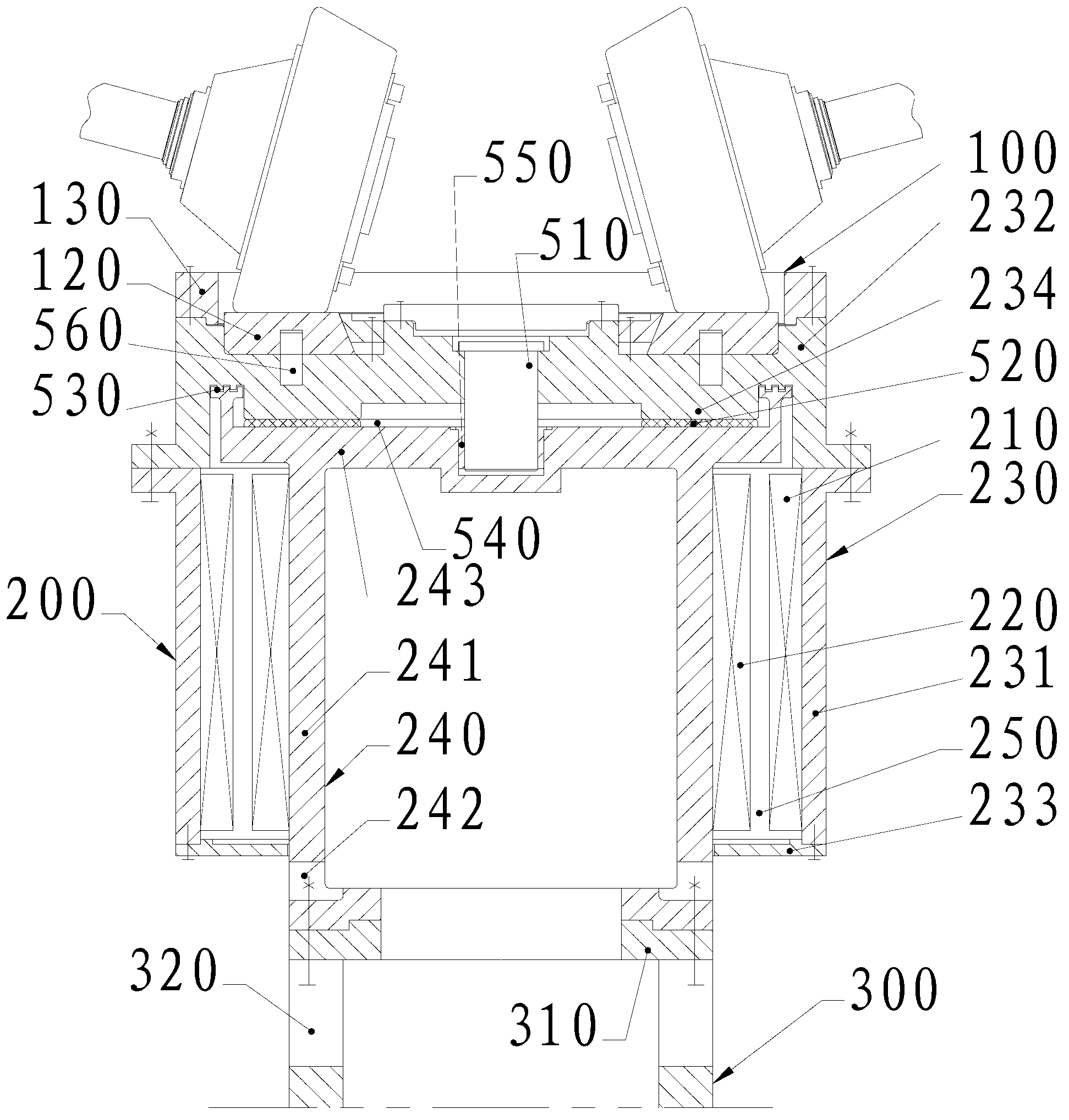
[0025] Such as figure 1 As shown, the vertical roller mill includes a motor 200, a grinding disc device 100, and a base 300. The motor 200 adopts a permanent magnet synchronous motor including a matched rotor 210 and a stator 220, and is used to install the rotor 210 and rotate with the rotor 210. The rotating body 230, the base 240 for fixing the stator 220, and the centering device for ensuring the radial fit clearance between the rotor 210 and the stator 220; 231 and top mounting plate 232, the base 240 and the stator 220 fixedly installed on the base 240 are located in the drum 231, the rotor 210 is fixed on the inner wall of the drum 231; the bottom of the base 240 and the base 300 Fixedly connected, the top mounting plate 232 is rotatably matched with the machine base 240 and supported and fixed by the top of the machine base 240, the top of the rotating cylinder 231 is fixedly connected with the top mounting plate 232, and the grinding disc device 100 is fixedly install...

Embodiment 2

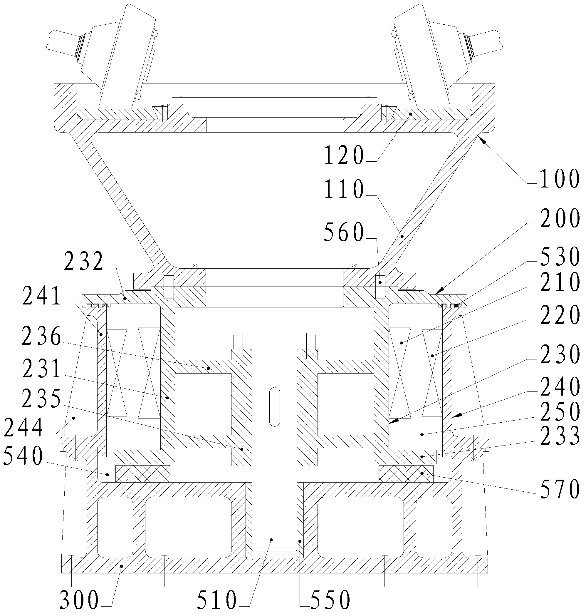
[0035] Such as figure 2 As shown, the vertical roller mill includes a motor 200, a grinding disc device 100, and a base 300. The motor 200 adopts a permanent magnet synchronous motor including a matched rotor 210 and a stator 220, and is used to install the rotor 210 and rotate with the rotor 210. The rotating body 230, the base 240 for fixing the stator 220, and the centering device for ensuring the radial fit clearance between the rotor 210 and the stator 220; 231 and top mounting plate 232, the rotating cylinder 231 and the rotor 210 fixedly installed on the rotating cylinder 231 are all located in the cylinder 241, the stator 220 is fixedly installed on the inner wall of the cylinder 241; the bottom of the base 240 and the base 300 Fixedly connected, the top of the rotating cylinder 231 is fixedly connected with the top mounting plate 232, the bottom of the rotating cylinder 231 is supported by the base 300, and the top mounting plate 232 is supported by the base 300 thro...


PUM


Abstract

The invention relates to grinding equipment, and in particular relates to a vertical roller mill which is widely used in a building material industry for grinding cement raw materials, cement clinker, slag and fire coal powder. A motor base comprises a cylinder for containing a stator; a motor rotating body comprises a rotary drum for containing a rotor, and a top installation plate; the top of the rotary drum is fixedly connected with the top installation plate; the cylinder and the rotary drum are sleeved; the bottom of the base is fixedly connected with a bottom seat; the top installation plate is in contact with and supported by the top of the base or by the bottom seat through the rotary drum; the supporting position of the top installation plate corresponds to the rolling position of a milling disk device; a centering device adopts a centering shaft which is arranged between the base and the rotating body or between the bottom seat and the rotating body; and the milling disk device is fixedly arranged on the top installation plate, and is directly driven by a motor to axially rotate around the motor. The top installation plate is supported by a cylindrical structure without influence of bending moment, and thus the vertical roller mill steadily operates, and is convenient to process, low in cost, energy-saving and environment-friendly; and the risk of damage to the centering shaft is extremely low.

Description

technical field [0001] The invention relates to a grinding equipment, in particular to a vertical roller mill widely used in the building materials industry for grinding cement raw meal, cement clinker, slag and coal. Background technique [0002] Vertical roller mills are referred to as vertical mills for short, mainly including L / M mills produced by Loesche in Germany, UBE mills produced by Ube in Japan, Atox mills produced by FLS in Denmark, RM mills produced by KHD Humboldt and Pfeiffer MPS mill. Each of the above vertical mills is composed of a powder classifier, a grinding roller, a grinding disc, a pressurizing device, a reducer, a motor, a frame and a housing, etc. The main difference lies in the structural combination of the grinding roller and the grinding disc. [0003] Specifically, the grinding disc device of the vertical mill is directly placed on the output flange of the special reducer, usually the output flange is connected to the bottom of the grinding dis...

Claims


Application Information

Patent Timeline
Patent Type & Authority Applications(China)
IPC IPC(8): B02C15/00H02K5/04H02K5/24
Inventor 洪盛荣周洲陈远
Owner CHINA ERZHONG GRP DEYANG HEAVY IND
Why Eureka
Try Eureka