Rocket engine jet pipe brazing strip automatic rolling point welding machine and rolling point welding process

A technology of rolling point welding machine and rocket engine, which is applied in welding equipment, manufacturing tools, metal processing, etc., can solve the problems of time-consuming, labor-intensive and low work efficiency, and achieves time-saving and labor-saving operation, good welding quality, and improved welding work efficiency. Effect

Active Publication Date: 2013-07-10
ZHANGJIAKOU NORTH WELDING MACHINE CO LTD
View PDF6 Cites 12 Cited by
  • Summary
  • Abstract
  • Description
  • Claims
  • Application Information

AI Technical Summary

Problems solved by technology

[0004] One of the purposes of the present invention is to provide a special automatic rolling spot welding machine for rocket engine nozzle solder strip rolling spot welding, to solve the low work efficiency and time-consuming that existing rocket engine nozzle solder strips are all welded manually strenuous problem

Method used


Image

  • Rocket engine jet pipe brazing strip automatic rolling point welding machine and rolling point welding process
  • Rocket engine jet pipe brazing strip automatic rolling point welding machine and rolling point welding process
  • Rocket engine jet pipe brazing strip automatic rolling point welding machine and rolling point welding process

Examples


Embodiment 1

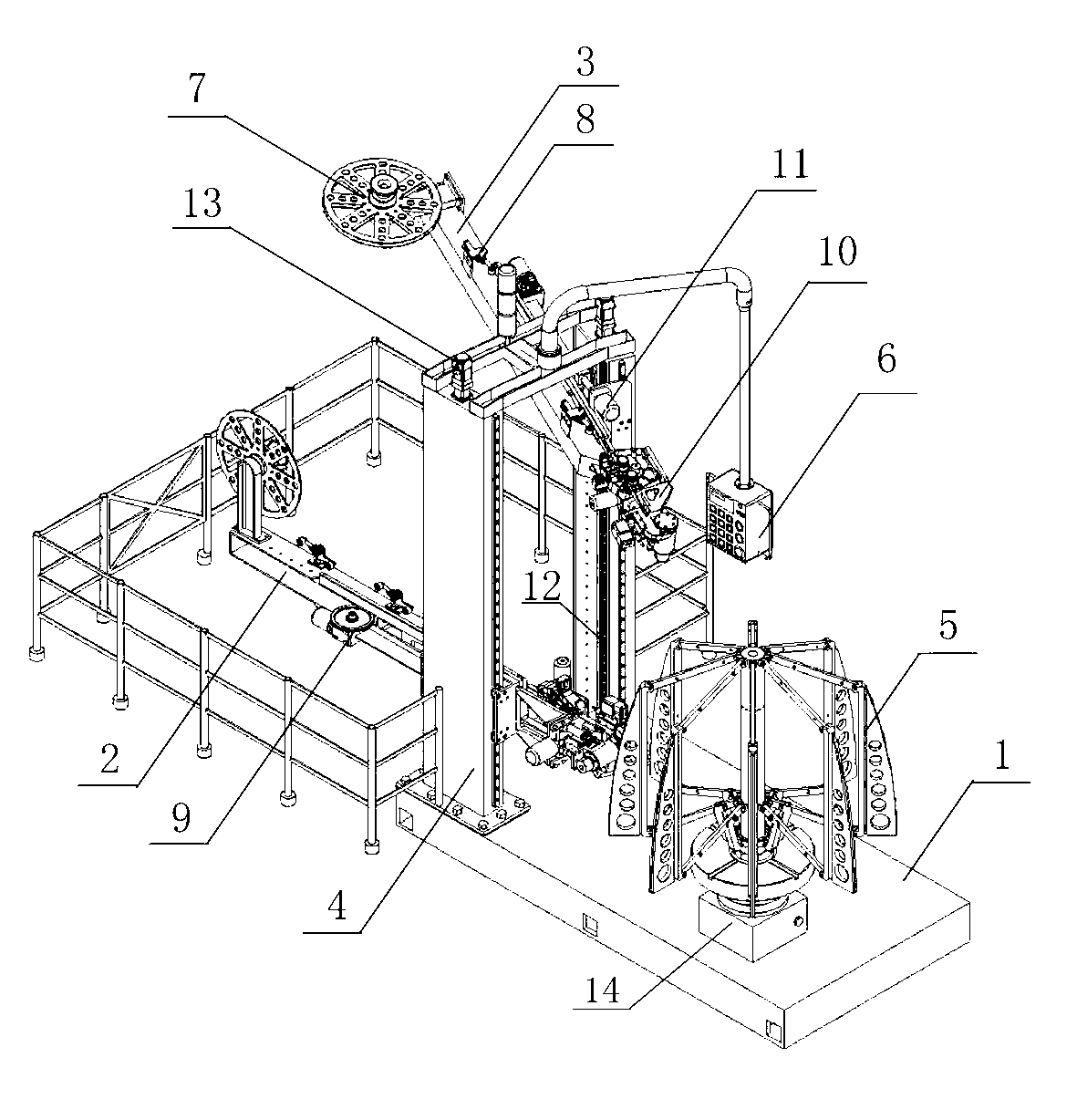
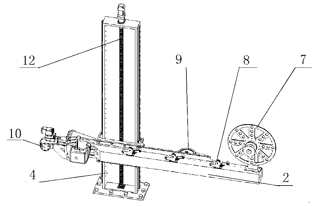
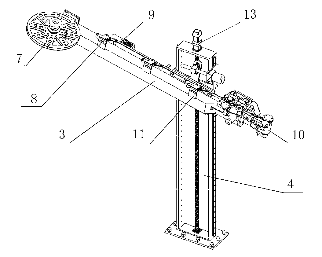
[0050] like figure 1 As shown, the automatic rolling spot welding machine for the rocket engine nozzle brazing material belt of the present invention includes a bed base 1, a rotary table 14, a tensioning mold 5, a portal support 4, a lead screw 12, a servo motor 13, Longitudinal rolling spot welding operation manipulator 2, circumferential rolling spot welding operation manipulator 3, solder belt rolling spot welding head 10, angle adjustment mechanism 11, solder belt positioning guide buffer mechanism 8, solder belt reel 7 and controller 6 Wait.

[0051] A rotary table 14 is arranged on the table at one end of the bed base 1, and a door-shaped support 4 and a peripheral guardrail are installed at the other end. On the rotary table 14, a stretching mold 5 for supporting the workpiece of the nozzle is installed. Leading screws 12 are respectively installed in the two columns of the door-shaped support 4 , and servo motors 13 which respectively drive the two leading screws to...

Embodiment 2

[0059] Rocket engine nozzle solder strip rolling spot welding process of the present invention comprises three major steps:

[0060] Step 1: Prepare the brazing filler metal strips for longitudinal rolling spot welding and circumferential rolling spot welding respectively, and wind the two kinds of brazing filler metal ribbons made on a brazing filler metal strip reel 7 respectively, and then wrap the two brazing filler metals The tape reel 7 is correspondingly installed on the longitudinal rolling spot welding operation manipulator 2 and the circumferential rolling spot welding operation manipulator 3, and the solder tape is pulled out from the solder tape reel 7, and is guided to the solder tape roll along the guide belt groove plate 20. The tape guide nozzle 16 at the front end of the spot welding machine head 10.

[0061] The preparation method of the solder strip is as follows: firstly, the solder plate is cut into several solder strips according to the set width. This p...


PUM

PropertyMeasurementUnit
widthaaaaaaaaaa
widthaaaaaaaaaa

Abstract

The invention relates to a rocket engine jet pipe brazing strip automatic rolling point welding machine and a rolling point welding process. The automatic rolling point welding machine comprises a body base, a rotating workbench, a tensioning pattern, a gate type support, a brazing strip disc, a controller, an angle adjusting mechanism, a longitudinal rolling point welding operating mechanical arm, an annular rolling point welding operating mechanical arm and the like. By the automatic rolling point welding machine, mechanical, automatic and intelligent longitudinal brazing strip and annular brazing strip rolling point welding are achieved on jet pipe components, welding efficiency is high, welding quality is good, welding point distances are adjustable, rolling point welding speed can be reach 3 points / second, and welding speed can reach more than 5 meters / second. The automatic rolling point welding machine has no noise, arc, splash, radiation and the like during welding, and is high in reliability, simple to operate, easy to maintain, and suitable for welding of rocket engine spraying pipes with the diameters of 260-1500mm.

Description

technical field [0001] The invention relates to a roll point welding device and a roll point welding process, in particular to an automatic roll point welding machine and a roll point welding process for a rocket engine nozzle solder belt. Background technique [0002] The welding process of the rocket engine nozzle parent body and the solder foil is a complex process technology, and the manual single-point welding process is usually used in China. The process is as follows: first cut the 0.15-0.2mm thick solder foil plate into 1.5-20mm wide strips through the roller shearing machine, limited by the length of the solder foil plate, the solder strips after cutting can only be messy Place it; then purify the cut solder strip for use; when welding, first stick the solder strip on the welding position on the nozzle of the rocket engine, and then hold a spot welding gun for point-by-point welding. [0003] There are problems with this welding process. First, when the length of t...

Claims


Application Information

Patent Timeline
Patent Type & Authority Applications(China)
IPC IPC(8): B23K3/00B23K1/00B23K3/06
Inventor 崔保崑
Owner ZHANGJIAKOU NORTH WELDING MACHINE CO LTD
Why Eureka
Try Eureka