
A Microwave Photonic Filter Structure Realizing Complex Coefficients

A filter structure and microwave photon technology, which is applied in the fields of high-speed wireless communication, digital satellite communication, high-speed optical fiber wireless access, microwave photon communication, and can solve the problems of high cost and high system control requirements

Inactive Publication Date: 2016-06-15
SOUTHWEST JIAOTONG UNIV
View PDF2 Cites 2 Cited by
  • Summary
  • Abstract
  • Description
  • Claims
  • Application Information

AI Technical Summary

Problems solved by technology

At present, most complex coefficient microwave photonic filters are based on the design scheme of two light sources, the cost is relatively high, and the control of the phase difference change is mainly realized by adjusting the bias voltage or changing the output wavelength of the light source, and the system control requirements are relatively high.

Method used


Image

  • A Microwave Photonic Filter Structure Realizing Complex Coefficients
  • A Microwave Photonic Filter Structure Realizing Complex Coefficients
  • A Microwave Photonic Filter Structure Realizing Complex Coefficients

Examples


Embodiment Construction

[0019] The present invention will be further described below in conjunction with the accompanying drawings.

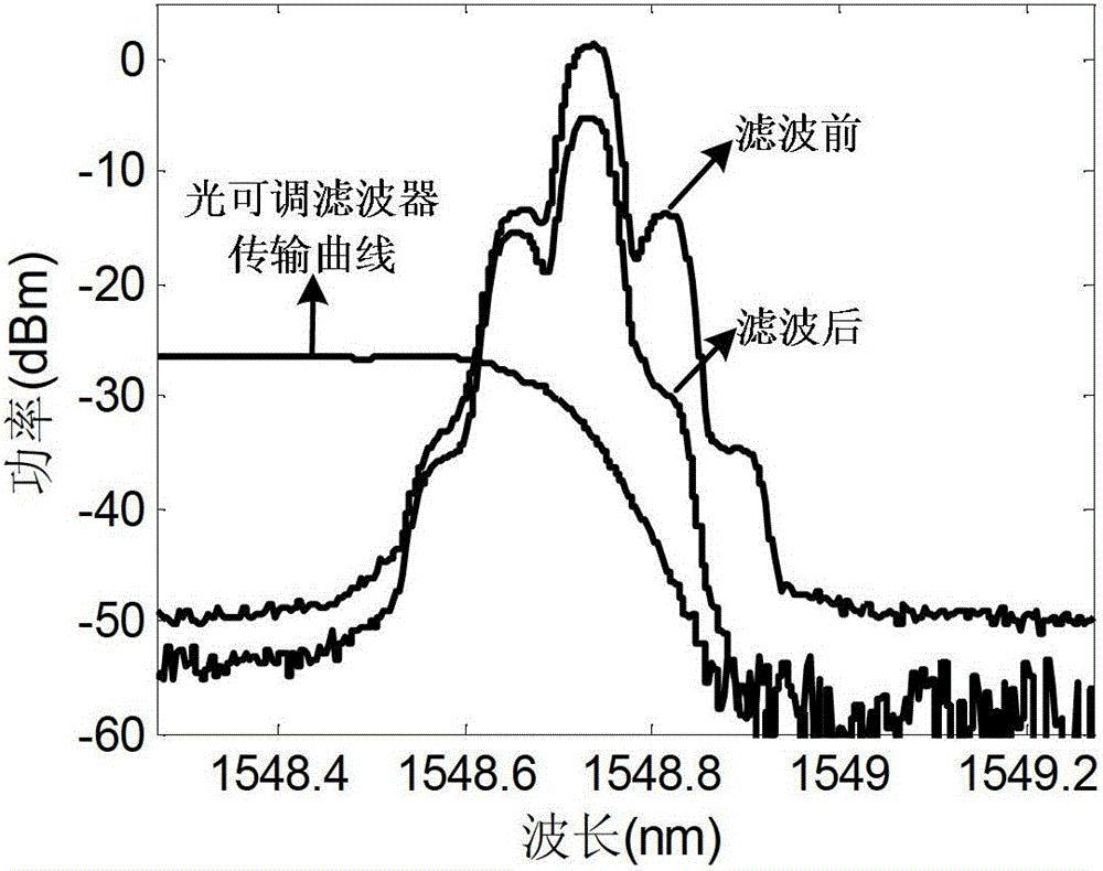
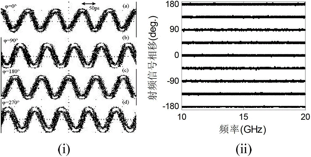
[0020] figure 1 It is a structural schematic diagram of the complex coefficient microwave photon filter of the present invention. The linearly polarized light generated by the tunable light source 101 is incident into the polarization modulator 102 at an angle of 45 degrees, and a microwave signal is loaded at the same time. After the polarization-modulated optical signal is incident on the optical tunable filter 103, the 3dB optical coupler 104 divides the optical signal into two beams. Wherein, one optical signal enters one input end of the polarizing beam splitter 107 after passing through the adjustable delay line 105 , and the other optical signal enters the other input end of the polarizing beam splitter 107 after passing through the optical attenuator 106 . The optical signal output from the output end of the polarization beam splitter 107 is incident into the...


PUM


Abstract

The invention discloses a microwave photonic filter structure capable of realizing complex coefficient. The structure consists of a laser source (101), a light path sequential connection polarization modulator (102), an optical tunable filter (103), an optical coupler (104), an optical adjustable delay line (105), an optical attenuator (106), a polarization beam splitter (107) and a photoelectric detector (108). The structure has the advantages that the microwave photonic filter has the complex coefficient characteristic; and compared with the negative coefficient filter, the free frequency spectrum range is not changed while the central wavelength of the filter can be adjusted. Compared with the scheme of the conventional complex coefficient microwave photonic filter, the structure can be realized only by one light source, so that the cost is reduced. The tunability of the filter can be realized only by changing the polarization detection direction of an optical signal, so that the adjustment is convenient.

Description

technical field [0001] The invention belongs to the field of microwave photon communication, and in particular relates to radio frequency filtering technology in microwave photon signal processing, which can be applied to the fields of high-speed wireless communication, digital satellite communication, high-speed optical fiber wireless access and the like. Background technique [0002] Compared with traditional electronic methods, microwave photonics technology has significant advantages in broadband processing, low loss and anti-electromagnetic interference, etc., and has been widely used in practical life. [0003] As an important research direction of microwave photonics, microwave photonic filter has become one of the research focuses of microwave photonics for many years. Usually, the design and realization of most microwave photonic filters are based on two-tap or multi-tap time-delay structures, and the coefficients are positive. Because only positive coefficients ca...

Claims


Application Information

Patent Timeline
Patent Type & Authority Patents(China)
IPC IPC(8): G02F1/01H04B10/70
Inventor 闫连山张程姜恒云潘炜罗斌邹喜华
Owner SOUTHWEST JIAOTONG UNIV
Learn More