Liquid sulfur collection method for sulfur recovery

A sulfur recovery and collection method technology, applied in chemical instruments and methods, sulfur compounds, inorganic chemistry, etc., can solve problems such as soil pollution, reduce emission concentration and total emission, process technology is safe and reliable, and reduce leakage and pollution sources Effect

Active Publication Date: 2014-10-15
SHANDONG SUNWAY PETROCHEMICAL ENGINEERING CO LTD
View PDF2 Cites 18 Cited by
  • Summary
  • Abstract
  • Description
  • Claims
  • Application Information

AI Technical Summary

Problems solved by technology

[0003] In the current sulfur recovery device, the liquid sulfur formed after the process gas is condensed and cooled is collected through the sulfur sealing tank. The height of the sulfur sealing tank is about 4 meters. In order to meet the process requirements, the sulfur sealing tank must be installed nearly three meters below the ground In the deep tank pool, the liquid sulfur directly flows into the liquid sulfur pool operated at normal pressure after being sealed with sulfur. In order to ensure that the liquid sulfur can flow into the liquid sulfur pool by itself, the liquid sulfur pool must also be installed below the ground. It is a concrete structure, which constitutes a harmful factor for soil pollution

Method used


Image

  • Liquid sulfur collection method for sulfur recovery
  • Liquid sulfur collection method for sulfur recovery

Examples


Embodiment 1

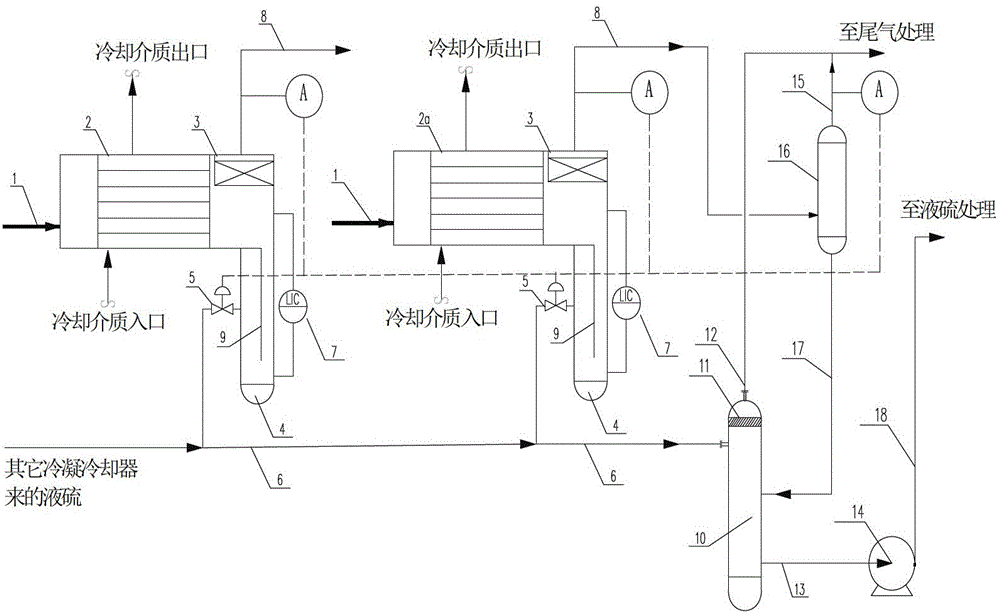
[0036] like figure 1The liquid sulfur collection device of the sulfur recovery device shown includes a sulfur condensation cooling and collection facility consisting of a process gas condensation cooler 2 and a liquid sulfur collection device 4, a liquid sulfur intermediate tank 10, a liquid sulfur pump 14, and a tail gas separator tank 16. The process gas outlet of the process gas condensing cooler 2 is provided with a liquid sulfur trap 3, the process gas outlet is connected to the process gas outlet line 8, and the process gas outlet line 8 is connected to the next-stage reaction or condensing cooling system or tail gas separator tank 16 , the top of the tail gas liquid separation tank 16 is connected to the tail gas treatment device through the tail gas discharge line 15, and the bottom of the tail gas liquid separation tank 16 is connected to the liquid sulfur intermediate tank 10 through the liquid sulfur pipeline 17; the liquid sulfur collector 4 is directly connected to...

Embodiment 2

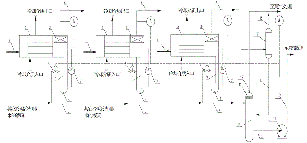
[0044] like figure 2 The liquid sulfur collection device of the sulfur recovery device shown includes a sulfur condensation cooling and collection facility consisting of a process gas condensation cooler 2 and a liquid sulfur collection device 4, a liquid sulfur intermediate tank 10, a liquid sulfur pump 14, and a tail gas separator tank 16. The process gas outlet of the process gas condensing cooler 2 is provided with a liquid sulfur trap 3, the process gas outlet is connected to the process gas outlet line 8, and the process gas outlet line 8 is connected to the next-stage reaction or condensing cooling system or tail gas separator tank 16 , the top of the tail gas liquid separation tank 16 is connected to the tail gas treatment device through the tail gas discharge line 15, and the bottom of the tail gas liquid separation tank 16 is connected to the liquid sulfur intermediate tank 10 through the liquid sulfur pipeline 17; the liquid sulfur collector 4 is directly connected ...

Embodiment 3

[0052] like figure 2 The liquid sulfur collection device of the sulfur recovery device shown includes a sulfur condensation cooling and collection facility consisting of a process gas condensation cooler 2 and a liquid sulfur collection device 4, a liquid sulfur intermediate tank 10, a liquid sulfur pump 14, and a tail gas separator tank 16. The process gas outlet of the process gas condensing cooler 2 is provided with a liquid sulfur trap 3, the process gas outlet is connected to the process gas outlet line 8, and the process gas outlet line 8 is connected to the next-stage reaction or condensing cooling system or tail gas separator tank 16 , the top of the tail gas liquid separation tank 16 is connected to the tail gas treatment device through the tail gas discharge line 15, and the bottom of the tail gas liquid separation tank 16 is connected to the liquid sulfur intermediate tank 10 through the liquid sulfur pipeline 17; the liquid sulfur collector 4 is directly connected ...


PUM


Abstract

The invention discloses a liquid sulphur collecting method suitable for a sulfur recovery device. Process gas of the sulphur recovery device enters a process gas condensate cooler to carry out gas-liquid separation; condensed and separated gas enters the next stage of reaction or condensate cooling system after a liquid sulphur catcher traps the liquid sulphur; the condensed liquid sulphur is collected by a liquid sulphur collector below the process gas condensate cooler; the collecting process is controlled by a process operation module; the collected liquid sulphur is directly delivered to a sealed liquid sulphur middle tank with pressure; the liquid sulphur is fed to a liquid sulphur treatment system after passing through a liquid sulphur degassing pump after gas-liquid secondary separation; and the separate gas is separated from the final stage of process gas condensate cooler and enters a tail gas treatment unit together with the tail gas which is further separated by a tail gas delivery tank. By adopting the technology, arrangement of a sulphur sealing tank, a sulphur sealing tank pond and a liquid sulphur pond is concealed; the technologic process is shortened; the investment on the equipment is reduced; and pollution of the liquid sulphur, the hydrogen sulfide and related treatment technologies on the soil, environment and ground water quality is partially removed.

Description

technical field [0001] The invention relates to the technical field of sulfur recovery, in particular to a liquid sulfur collection method suitable for a sulfur recovery device. Background technique [0002] my country has always advocated energy conservation and emission reduction, strictly controlled atmospheric sulfur dioxide emissions, paid attention to environmental protection, and protected soil from pollution. [0003] In the current sulfur recovery device, the liquid sulfur formed after the process gas is condensed and cooled is collected through the sulfur sealing tank. The height of the sulfur sealing tank is about 4 meters. In order to meet the process requirements, the sulfur sealing tank must be installed nearly three meters below the ground In the deep tank pool, the liquid sulfur directly flows into the liquid sulfur pool operated at normal pressure after being sealed with sulfur. In order to ensure that the liquid sulfur can flow into the liquid sulfur pool b...

Claims


Application Information

Patent Timeline
Patent Type & Authority Patents(China)
IPC IPC(8): C01B17/027
Inventor 刘桂玲高炬赵芳李铁军李英
Owner SHANDONG SUNWAY PETROCHEMICAL ENGINEERING CO LTD
Why Eureka
Try Eureka