Two-way reciprocal single longitudinal mode fiber ring cavity laser

A ring cavity and laser technology, applied in lasers, laser parts, phonon exciters, etc., can solve the problem of affecting the frequency stability and application range of lasers, the circular polarization state of light cannot be well maintained, and affecting system stability, etc. problems, to achieve the effect of suppressing the space hole burning effect, reducing the risk of research and development, and reducing the impact

Inactive Publication Date: 2015-06-24
UNIV OF SCI & TECH OF CHINA
View PDF2 Cites 2 Cited by
  • Summary
  • Abstract
  • Description
  • Claims
  • Application Information

AI Technical Summary

Problems solved by technology

For linearly polarized bidirectional single longitudinal mode erbium-doped fiber ring cavity lasers, due to the use of non-reciprocal devices to generate mutually orthogonal linearly polarized light, the optical paths of the two orthogonal linearly polarized lights in the clockwise and counterclockwise directions are different. Therefore, the eigenfrequency of the laser is different in the clockwise and counterclockwise directions, and there is a frequency offset. In this way, when the external environment changes (such as temperature changes), the frequency offset will fluctuate, which will affect the frequency stability and application range of the laser.
[0004] For circularly polarized bidirectional single longitudinal mode erbium-doped fiber ring cavity lasers, it is generally necessary to twist the pigtails of all devices to obtain a certain circular polarization maintaining capability, and the immaturity of fiber circular polarization maintaining technology and devices leads to The circular polarization state of light in the ring cavity cannot be well maintained, and it is easily affected by environmental factors such as vibration and temperature, which in turn affects the stability of the system

Method used


Image

  • Two-way reciprocal single longitudinal mode fiber ring cavity laser
  • Two-way reciprocal single longitudinal mode fiber ring cavity laser
  • Two-way reciprocal single longitudinal mode fiber ring cavity laser

Examples


Embodiment Construction

[0041] The technical solutions in the embodiments of the present invention will be clearly and completely described below in conjunction with the accompanying drawings in the embodiments of the present invention. Obviously, the described embodiments are only some of the embodiments of the present invention, not all of them. Based on the embodiments of the present invention, all other embodiments obtained by persons of ordinary skill in the art without making creative efforts belong to the protection scope of the present invention.

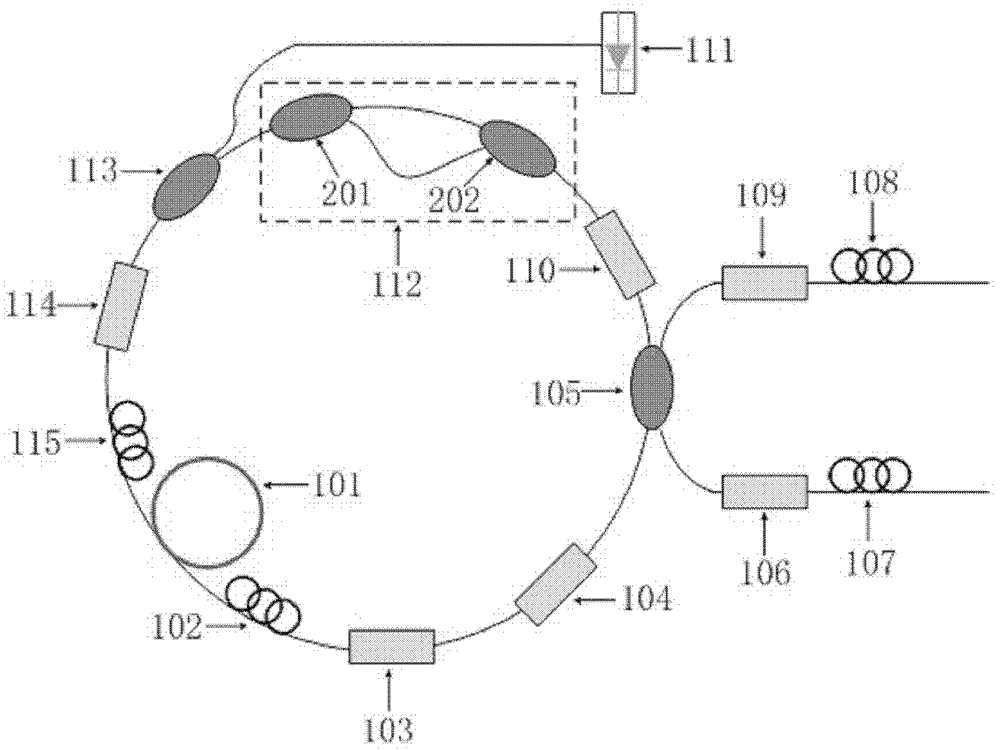
[0042]The scheme of combining linearly polarized light and circularly polarized light provided by the embodiment of the present invention can overcome the frequency bias fluctuation problem in the original linearly polarized system, reduce the use of circularly polarized light, reduce the risk of system development, and reduce the In order to understand the impact of the circular polarization state disturbance caused by environmental changes on syst...


PUM


Abstract

The invention discloses a two-way reciprocal single longitudinal mode fiber ring cavity laser. The two-way reciprocal single longitudinal mode fiber ring cavity laser comprises a rare-earth-doped fiber (101) which is subjected to torsion processing, a first polarization controller (102), a first polarization converter (103), a narrow-band filter (104), an output coupler (105), a two-way line polarizer (110), a fine filter (112), a wavelength division multiplexer (113), a second polarization converter (114), a second polarization controller (115), a pump laser (111), a first isolator (106), a second isolator (109), a third polarization controller (107) and a fourth polarization controller (108). The two-way reciprocal single longitudinal mode fiber ring cavity laser can effectively eliminate the spatial hole-burning effect, reduce the usage of circularly-polarized light, reduce the systematic research and development risk, and reduce the influence of polarization state disturbance caused by environmental changes on the system stability, thereby improving the performance of the two-way reciprocal single longitudinal mode fiber ring cavity laser.

Description

technical field [0001] The invention relates to the technical field of optical fiber communication, in particular to a bidirectional reciprocal single longitudinal mode fiber ring cavity laser. Background technique [0002] At present, in the field of optical fiber communication technology, fiber ring cavity laser has the advantages of low cost, compact structure, anti-electromagnetic interference, etc., and has a wide range of applications in the fields of optical fiber sensing, remote sensing and optical fiber communication. When the two beams of light propagating in opposite directions in the gain fiber form a standing wave, the spatial hole burning effect will occur, which will form a gain grating in the gain fiber, resulting in the coupling of the two beams of light propagating in opposite directions, thereby causing multiple longitudinal modes, modes competition effects. Therefore, in order to obtain a bidirectional single longitudinal mode laser, the spatial hole bur...

Claims


Application Information

Patent Timeline
Patent Type & Authority Patents(China)
IPC IPC(8): H01S3/067H01S3/101
Inventor 苏觉李科杨利钱景仁
Owner UNIV OF SCI & TECH OF CHINA
Why Eureka
Try Eureka