
Flushing system and method for cleaning local sedimentation in nuclear power plant

A technology for flushing systems and nuclear power plants, which is applied in the directions of cleaning methods, cleaning methods and utensils, chemical instruments and methods using liquids, etc., which can solve the problems of waste of resources, inability to measure pressure difference, inaccurate measurement of pressure difference, etc., and achieve economical savings. The effect of water use, improved operational safety, and increased utilization

Active Publication Date: 2013-07-24
CHINA NUCLEAR POWER ENG CO LTD
View PDF8 Cites 4 Cited by
  • Summary
  • Abstract
  • Description
  • Claims
  • Application Information

AI Technical Summary

Problems solved by technology

[0003] In the water intake pump room of the nuclear power plant in the high-sediment sea area, although the circulating water and the important plant water system have independent flow channels, which will not cause flow channel silting, the positions of the differential pressure gauge conduits in the system, the connection valves of the suction culvert, etc. It is easy to form sediment deposits, which will cause the problem of inaccurate or unable to measure the pressure difference, and the connection valve of the suction culvert cannot be opened
[0004] In addition, for nuclear power plants that use fresh water as the water source for desalinated water, the raw water for the desalinated water system generally comes from the production water system of the fresh water plant, and the water quality of the produced water generally meets the drinking water quality standard. Compared with seawater, ultrafiltration wastewater is very clean, if not recycled, it will cause serious waste of resources

Method used


Image

  • Flushing system and method for cleaning local sedimentation in nuclear power plant
  • Flushing system and method for cleaning local sedimentation in nuclear power plant

Examples


Embodiment Construction

[0015] The present invention will be further described below in conjunction with the accompanying drawings and specific embodiments.

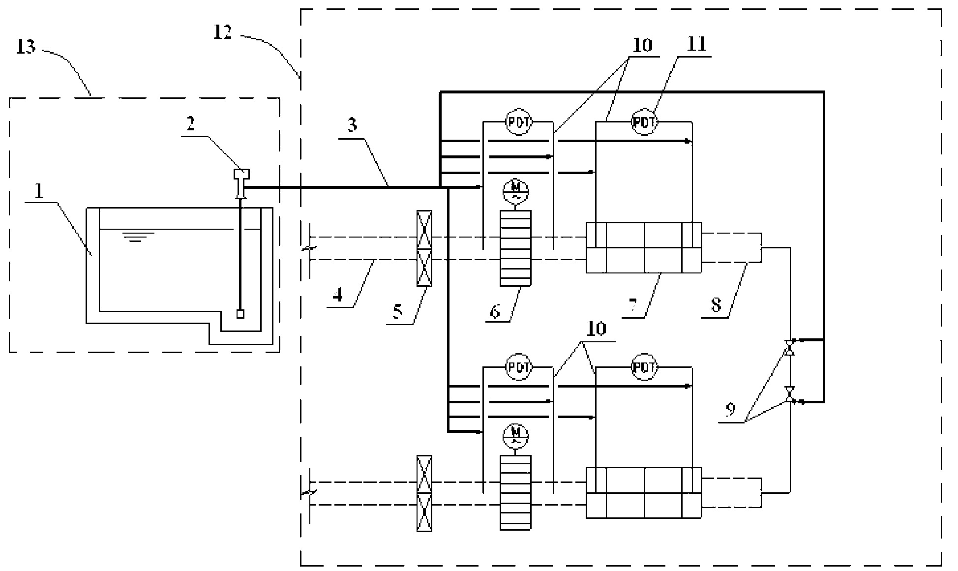
[0016] Such as figure 1 As shown, the desalinated water plant 13 is usually installed in the nuclear power plant, and the pretreatment process of the desalted water plant 13 generally adopts ultrafiltration treatment, and the waste water after the ultrafiltration treatment is used to flush the circulating water and important plant water in the pump room of the nuclear power plant System, circulating water and some pipelines in the important plant water system are located in the water intake pump room 12.

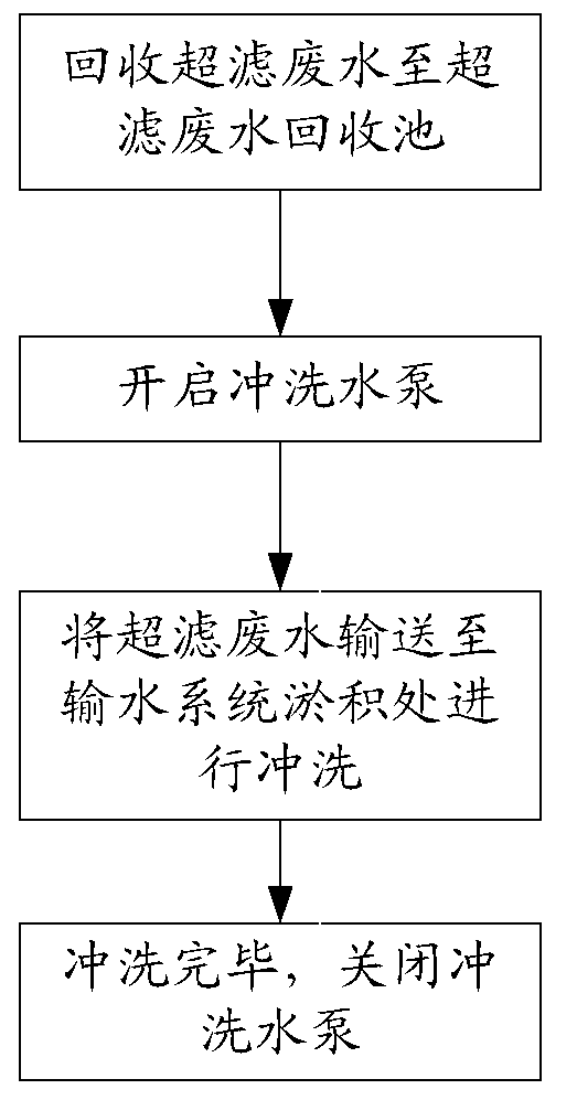
[0017] A flushing system for cleaning local deposits in nuclear power plants provided by the present invention includes an ultrafiltration wastewater recovery pool 1 and a flushing water pump 2 arranged in a desalinated water plant 13, the inlet end of the flushing water pump 2 and the ultrafiltration wastewater recovery pool 1 connected, an...


PUM


Abstract

The invention relates to a flushing system for cleaning local sedimentation in a nuclear power plant, wherein a demineralized water plant building (13) and a water taking pump room (12) of a circulation water and important plant use water system are arranged in the nuclear power plant, the flushing system comprises an ultrafiltration waste water recovery pool (1) and a flushing water pump (2), the ultrafiltration waste water recovery pool (1) is arranged in the demineralized water plant building (13), the inlet end of the flushing water pump (2) is connected with the ultrafiltration waste water recovery pool (1), and the outlet end of the flushing water pump (2) is provided with a flushing pipeline (3). The invention also provides a method adopting the flushing system for cleaning the local sedimentation in the nuclear power plant. When the flushing system and the method provided by the invention are adopted, the problem of local sedimentation of the pump room of the nuclear power plant in the high-sediment sea area is solved, the operation safety of the circulation water and important plant use water system in the pump room is improved, the utilization rate of fresh water is also improved, and the water consumption is saved.

Description

technical field [0001] The invention belongs to the technical field of guaranteeing safe operation of nuclear power plants, and in particular relates to a flushing system and method for cleaning local deposits in nuclear power plants. Background technique [0002] Usually, SEC / CRF drainage tunnel 4, SEC / CRF ram 5, SEC / CRF grid decontamination machine 6 (connected with motor, motor Indicated by symbol M), SEC / CRF drum filter 7, SEC / CRF suction culvert 8, etc. (such as figure 1 shown), and are connected together through pipelines. Generally, the system also has components such as a suction underdrain connection valve 9, a pressure gauge 11, and a differential pressure gauge conduit 10. [0003] In the water intake pump room of the nuclear power plant in the high-sediment sea area, although the circulating water and the important plant water system have independent flow channels, which will not cause flow channel silting, the positions of the differential pressure gauge condui...

Claims


Application Information

Patent Timeline
Patent Type & Authority Applications(China)
IPC IPC(8): B08B3/02
Inventor 闫红梅白玮宋建军王东海
Owner CHINA NUCLEAR POWER ENG CO LTD
Learn More