Green water flow estimation method and device

A technology of green water and water flow, applied in computing, special data processing applications, instruments, etc., can solve problems such as difficult to meet the accuracy requirements, cannot be widely promoted, and the inhomogeneity of the surface cannot accurately estimate the spatial distribution of a specific area, etc.

Active Publication Date: 2013-07-24
INST OF REMOTE SENSING & DIGITAL EARTH CHINESE ACADEMY OF SCI
View PDF0 Cites 7 Cited by
  • Summary
  • Abstract
  • Description
  • Claims
  • Application Information

AI Technical Summary

Problems solved by technology

[0005] Therefore, the inhomogeneity of the surface is not fully considered, resulting in the inability to accurately estimate the spatial distribution of a specific area, which has great limitations
[0006] The remote sensing green water flow estimation method fully considers the heterogeneity of the surface, discretizes the space ...

Method used


Image

  • Green water flow estimation method and device
  • Green water flow estimation method and device
  • Green water flow estimation method and device

Examples


Embodiment 1

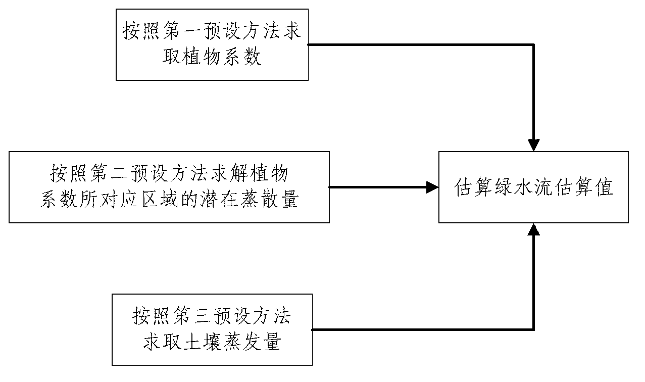
[0101] like figure 1 As shown, the method for estimating green water flow in this embodiment includes the following steps:

[0102] Step A: Calculating the plant coefficient K according to the first preset method c ;

[0103] Step B: Solve the plant coefficient K according to the second preset method c The potential evapotranspiration ET of the corresponding area p0 ;

[0104] Step C: Calculating the soil evaporation E according to the third preset method a ;

[0105] Step D: Estimate the estimated value Z of green water flow by the following formula,

[0106] ET p =K c ·ET p0

[0107] E. can,a =c p ×δ×ET p

[0108] T a = Σ i = 1 n S i

[0109] Z=E can,a +T a +E a

[0110] in,

[0111] ET p is the potential evapotranspiration of plants,

[0112] E. can,a is the intercepted stea...

Embodiment 2

[0138] The method for estimating green water flow in this embodiment includes the following steps:

[0139] Step A: Calculating the plant coefficient K according to the first preset method c ;

[0140] Step B: Solve the plant coefficient K according to the second preset method c The potential evapotranspiration ET of the corresponding area p0 ;

[0141] Step C: Calculating the soil evaporation E according to the third preset method a ;

[0142] Step D: Estimate the estimated value Z of green water flow by the following formula,

[0143] ET p =K c ·ET p0

[0144] E. can,a =c p ×δ×ET p

[0145] T a = Σ i = 1 n S i

[0146] Z=E can,a +T a +E a

[0147] in,

[0148] ET p is the potential evapotranspiration of plants,

[0149] E. can,a is the intercepted steam volume of the plant c...

Embodiment 3

[0169] The green water flow estimation method described in this embodiment is a further improvement on the basis of Embodiment 2. The second preset method calculates the vegetation coefficient K through the following formula c Potential evapotranspiration ET for the area being characterized p0

[0170] ET p 0 = 0.408 Δ ( R n - G ) + γ 900 T a + 273 U 2 ( e S - e...


PUM


Abstract

The invention discloses a green waterflow estimation method and a green waterflow estimation device. The green water estimation method is designed to solve the problem that the conventional green waterflowestimationmethod is not accurate. The green water estimation method comprises the following steps: A) solving a plant coefficient Kc according to a first preset method; B) solving potential evapotranspiration ETp0 of an area corresponding to the plant coefficient Kc according to a second preset method; C) solving soil evaporativeness Ea according to a third preset method; and D) estimating a green waterflow estimated value Z according to the following formulas: ETp=Kc*ETP0, Ecan,a=cp*delta*ETp, Z=Ecan,a+Ta+Ea, wherein ETp is plant potential evapotranspiration, Ecan,a is plant canopy interceptionevaporativeness, cp is a rate of plant coverage which is obtained by inverting space discretized pixel elements of a remote sensing image, delta is an area rate of a wet leaf area, Ta is plant transpiration, Si is water absorption of an i-layer root system, and n is the total number of layers of a plant root system. The invention has the advantages of simple implementation and accurate green waterflow simulation and estimation.

Description

technical field [0001] The invention relates to the scientific field of ecohydrology, in particular to a method and device for estimating green water flow. Background technique [0002] The green water flow usually includes three parts, which are the water vapor transpired by plants into the atmosphere, the water vapor trapped by the plant canopy during precipitation, and the water vapor evaporated from the soil into the air. [0003] The underlying surface refers to the earth's surface, including oceans, land, plateaus, mountains, plains, forests, grasslands, and cities on land. Parameters such as temperature, moisture, and surface shape of each part of the underlying surface are quite different, so the underlying surface has non-uniformity. [0004] The hydrology method, plant physiology method, and SPAC transport simulation method in the existing green water flow estimation methods are only applicable to relatively uniform underlying surfaces. Under normal circumstances...

Claims


Application Information

Patent Timeline
IPC IPC(8): G06F19/00
Inventor 王树东王玉娟张立福汲玉河杨杭吴太夏岑奕
Owner INST OF REMOTE SENSING & DIGITAL EARTH CHINESE ACADEMY OF SCI
Why Eureka
Try Eureka