Furnace type cooling and heat exchange device for sintered ores

A technology of heat exchange device and mine furnace, applied in furnaces, waste heat treatment, furnace components, etc., can solve the problems of rapid decay of waste heat utilization efficiency, low flue gas temperature, low waste heat utilization efficiency, etc., and avoid flue gas temperature and flue gas volume. Fluctuation of flue gas, increasing flue gas temperature, and improving cooling effect

Active Publication Date: 2013-08-07
CITIC HEAVY INDUSTRIES CO LTD +1
View PDF7 Cites 21 Cited by
  • Summary
  • Abstract
  • Description
  • Claims
  • Application Information

AI Technical Summary

Problems solved by technology

At present, my country's sinter cooling and heat exchange and waste heat recovery and utilization mainly adopt ring cooling or belt cooling technology, "Research on Waste Heat Recovery and Utilization of Sintering Process" (Zhang Weiliang, Ma Zhongmin, Zhou Haiping. Nonferrous Metallurgy Energy Conservation [J]. 2011, (27) 1: 47-50), "Sintering Ring Cold Waste Heat Recovery Power Generation Technology Characteristics and Application" (Shi Baodong, Liu Ye, Yuan Weibiao, etc. Metallurgical Power [J]. 2011(1): 53-55) and many other studies have shown that using the above The sinter cooling method has the following disadvantages: ①The waste heat parameters fluctuate greatly, which endangers the safety of the waste heat utilization system; ②The air leakage problem of the system is difficult to solve, the waste heat utilization efficiency decays quickly, and the leakage of smoke and dust pollutes the operating environment; ③The flue gas temperature is low (Generally 300°C-400°C), waste heat utilization efficiency is low
Therefore, it is of great significance to develop cooling equipment that efficiently cools sinter and recovers waste heat. However, the layout of new cooling equipment will be limited by the original equipment site, making it difficult to implement.

Method used


Image

  • Furnace type cooling and heat exchange device for sintered ores
  • Furnace type cooling and heat exchange device for sintered ores

Examples


Embodiment Construction

[0013] The present invention will be further described in detail below in conjunction with the accompanying drawings and specific embodiments.

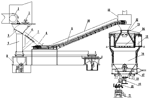
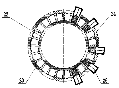
[0014] Such as figure 1 and figure 2 As shown, a sinter furnace type cooling heat exchange device includes a sintering machine 1, a single roll crusher 2, a flap valve 3, a thermal vibrating screen 6, a chain plate conveyor 9, a material distribution device 13, a cooling furnace, and an air distribution device 17. Discharging device and belt conveyor 21, the outlet of the sintering machine 1 is provided with a single-roll crusher 2, the bottom of the single-roll crusher 2 is provided with a flap valve 3, and the bottom of the flap valve 3 is arranged in the chute of the furnace cooling system 4 and the chute 5 of the ring cooling / band cooling system, the flap valve 3 can switch between the chute 4 of the furnace cooling system and the chute 5 of the ring cooling / band cooling system; The bottom of the heat vibrating screen 6 is conn...


PUM


Abstract

The invention discloses a furnace type cooling and heat exchange device for sintered ores and relates to the technical field of cooling devices of sintered ores. A single-roll crusher is arranged at an outlet of a sintering machine, a flap valve is arranged under the single-roll crusher, the bottom of the flap valve is arranged at the connection position of a furnace cooling system chute and an annular cooling system chute / a belt cooling system chute, the flap valve can be switched between the furnace cooling system chute and the annular cooling system chute / the belt cooling system chute, a hot vibration screen also serves as the bottom wall of the furnace cooling system chute, a hot return mine chute is connected under the hot vibration screen and is connected with the annular cooling system chute / the belt cooling system chute, an outlet of the furnace cooling system chute is connected with one end of a chain-scraper conveyor, the other end of the chain-scraper conveyor is connected with a fire door of a cooling furnace, and a heat-insulating cover is arranged above the chain-scraper conveyor. By the aid of the device, the cooling effect and the waste heat utilization ratio of sintered ores are effectively improved, and the furnace cooling system device can be arranged in a remote distance without being limited by fields.

Description

technical field [0001] The invention relates to the technical field of sinter cooling equipment, in particular to a sinter furnace cooling heat exchange device. Background technique [0002] my country is a country that consumes a lot of energy. In order to vigorously promote energy-saving and environmental protection technologies and improve the comprehensive utilization efficiency of energy, the country has proposed a series of encouraging and preferential policies. The iron and steel industry is a large energy consumer in my country, accounting for about 15% of the total energy consumption in the country. In the process of iron and steel production, the energy consumption of the sintering process ranks second, and the sensible heat of sintering production in sintering production accounts for more than 40% of the total heat consumption. Sintering energy saving is very important. Efficient recovery and utilization of sensible heat of sinter is an effective way to improve th...

Claims


Application Information

Patent Timeline
Patent Type & Authority Applications(China)
IPC IPC(8): F27D15/02F27B21/08F27D3/00F27D17/00
CPCY02P10/25
Inventor 程波彭岩王继生郭存红李建强张侃仓鲍东南
Owner CITIC HEAVY INDUSTRIES CO LTD
Why Eureka
Try Eureka