Sintered ore cooling furnace

A technology for sintering and cooling furnaces, which is applied in the direction of furnaces, furnace components, and the treatment of discharged materials. It can solve the problems of large fluctuations in waste heat parameters, fast decay of waste heat utilization efficiency, and low waste heat utilization efficiency. Consistent, avoiding fluctuating flue gas temperature and flue gas volume, and improving service life

Active Publication Date: 2013-08-07
中信重工工程技术有限责任公司
View PDF6 Cites 23 Cited by
  • Summary
  • Abstract
  • Description
  • Claims
  • Application Information

AI Technical Summary

Problems solved by technology

[0004] When adopting the above sinter cooling method, the waste heat utilization has the following disadvantages: ①The waste heat parameters fluctuate greatly, which endangers the safety of the waste heat utilization system; The air temperature is low (generally 300°C ~ 400°C), and the waste heat utilization efficiency is low
[0005] Furnace cooling can solve the above problems, but the traditional cooling furnace structure also has the following problems: 1. The inner ring of the annular air duct is easy to collapse; 2. The corbel bricks in the ramp area are easy to crack, collapse and wear; 3. The cooling area Refractory bricks are easy to wear

Method used


Image

  • Sintered ore cooling furnace
  • Sintered ore cooling furnace
  • Sintered ore cooling furnace

Examples


Embodiment Construction

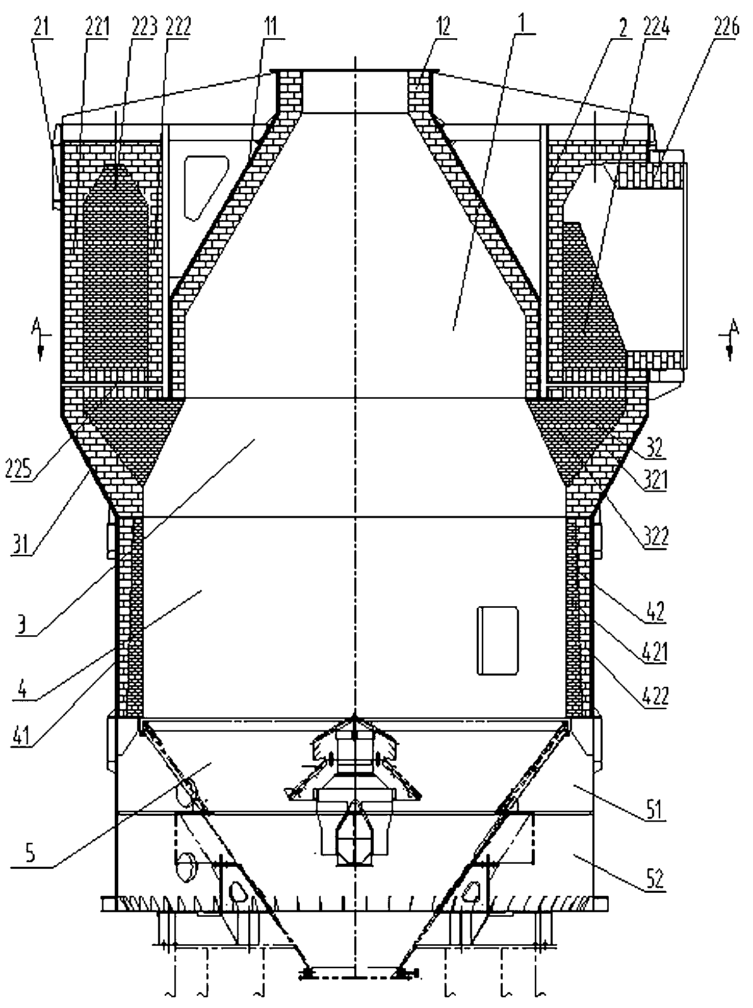
[0029] As shown in the figure, a sinter cooling furnace includes a pre-storage area 1, an annular air channel area 2, a chute area 3, a cooling area 4 and an air chamber 5, and the periphery of the pre-storage area 1 is provided with an annular air channel area 2 , the ramp area 3, the cooling area 4 and the air chamber 5 are sequentially arranged below the pre-storage area 1 from top to bottom;

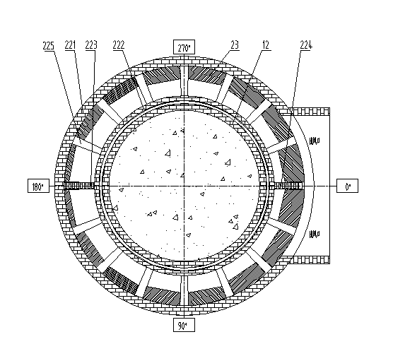
[0030] The annular airway area 2 includes a steel structure shell I21, a brick structure wall I22 and an air regulating plate 23, and ceramic fiber blankets are filled between the steel structure shell I21 and the brick structure wall I22, and the brick structure wall I22 includes The outer ring wall 221, the inner ring wall 222, the rectangular partition wall 223, the triangular partition wall 224, the radial support column 225 and the hot air outlet 226, and the outer ring wall 221 and the inner ring wall 222 are built into one at the top , forming an n-shaped annular cavity with a...


PUM


Abstract

The invention discloses a sintered ore cooling furnace device. The device is composed of a pre-storage area, an annular air flue area, a chute area, a cooling area and an air chamber. High-temperature sintered ores are continuously and evenly distributed into a cooling furnace for cooling through a charging port above the pre-storage area by a material distribution device, high-temperature sintered ores are subjected to counter-flow heat exchange with low-temperature air blown from the bottom of the furnace in the cooling area of the cooling furnace, sintered ores are cooled to below 180 DEG C, low-temperature ores are discharged by a discharging device, the low-temperature air is heated to about 600 DEG C through counter-flow heat exchange and enters a waste heat recycling system through an air outlet, and hot air and hot sintered ores are effectively sealed inside the cooling furnace in the whole process. By the aid of the device, on the premise that the quality of sintered ores is guaranteed or improved and the return fine rate is reduced, the efficiency of recycling of waste heat of sintered ores is improved to the maximum extent.

Description

technical field [0001] The invention relates to a cooling device, in particular to a sinter cooling furnace. Background technique [0002] my country is a country that consumes a lot of energy. In order to vigorously promote energy-saving and environmental protection technologies and improve the comprehensive utilization efficiency of energy, the country has proposed a series of encouraging and preferential policies. The iron and steel industry is a large energy consumer in my country, accounting for about 15% of the total energy consumption in the country. In the process of iron and steel production, the energy consumption of the sintering process ranks second, and the sensible heat of sintering production in sintering production accounts for more than 40% of the total heat consumption. Sintering energy saving is very important. Efficient recovery and utilization of sensible heat of sinter is an effective way to improve the energy efficiency of the iron and steel industry. ...

Claims


Application Information

Patent Timeline
Patent Type & Authority Applications(China)
IPC IPC(8): F27D15/02F27D17/00
CPCY02P10/25
Inventor 王继生程波彭岩张晔乔文存李建强张明灿李书磊王小英
Owner 中信重工工程技术有限责任公司
Why Eureka
Try Eureka