Pressure sensor utilizing electrostatic negative stiffness and production method of pressure sensor

A technology of pressure sensor and negative stiffness, which is applied in the direction of measuring fluid pressure through electromagnetic components, measuring fluid pressure, measuring force by measuring the frequency change of stressed vibrating elements, etc., can solve the problem that the quality factor is difficult to reach the cantilever beam resonance structure. Tens of thousands of levels, high-precision pressure sensor design increases difficulty, pressure measurement temperature error and other issues, to achieve the effect of reducing design difficulty, improving signal-to-noise ratio, and improving measurement accuracy

Active Publication Date: 2013-08-07
XIAMEN UNIV
View PDF7 Cites 8 Cited by
  • Summary
  • Abstract
  • Description
  • Claims
  • Application Information

AI Technical Summary

Problems solved by technology

The above working principles make this type of resonant structure at least double-ended or even multi-terminal fixed, which will make it difficult for the quality factor of this type of structure to reach the level of 100,000 that can be achieved by a cantilever beam resonant structure.
Another important problem with this type of resonant structure is that changes in temperature will cause deformation of the pressure sensitive membrane, which will eventually affect the resonant frequency of the output, resulting in temperature errors in pressure measurement, which increases the difficulty of designing high-precision pressure sensors.

Method used


Image

  • Pressure sensor utilizing electrostatic negative stiffness and production method of pressure sensor
  • Pressure sensor utilizing electrostatic negative stiffness and production method of pressure sensor
  • Pressure sensor utilizing electrostatic negative stiffness and production method of pressure sensor

Examples


Embodiment Construction

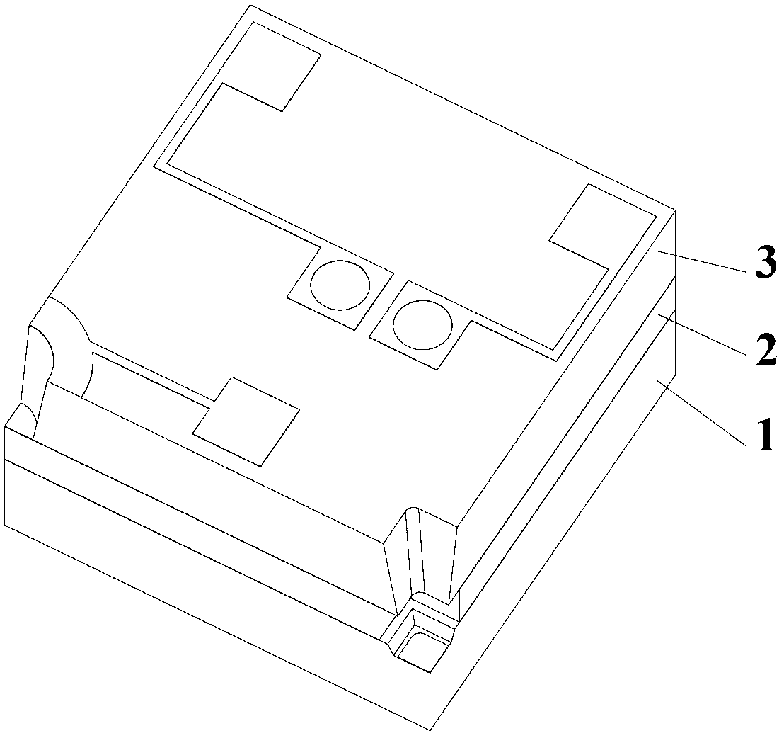
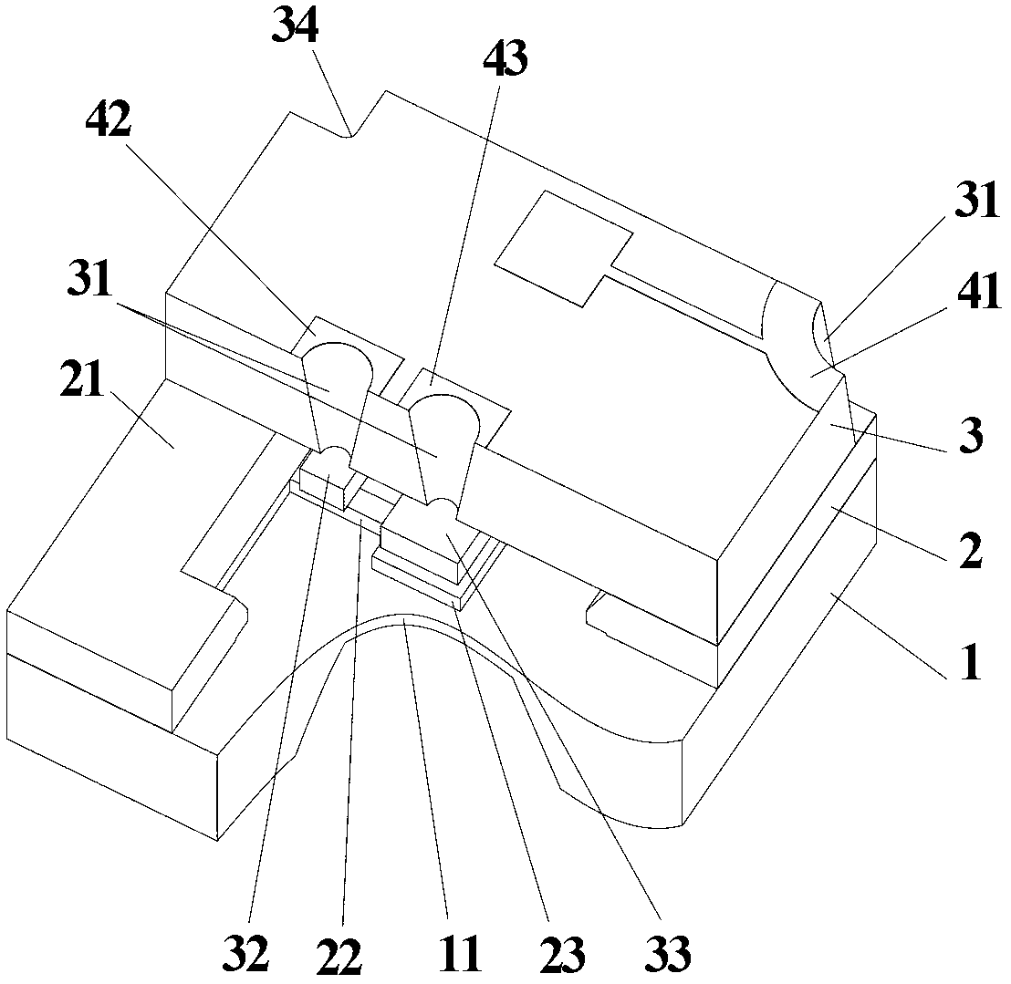
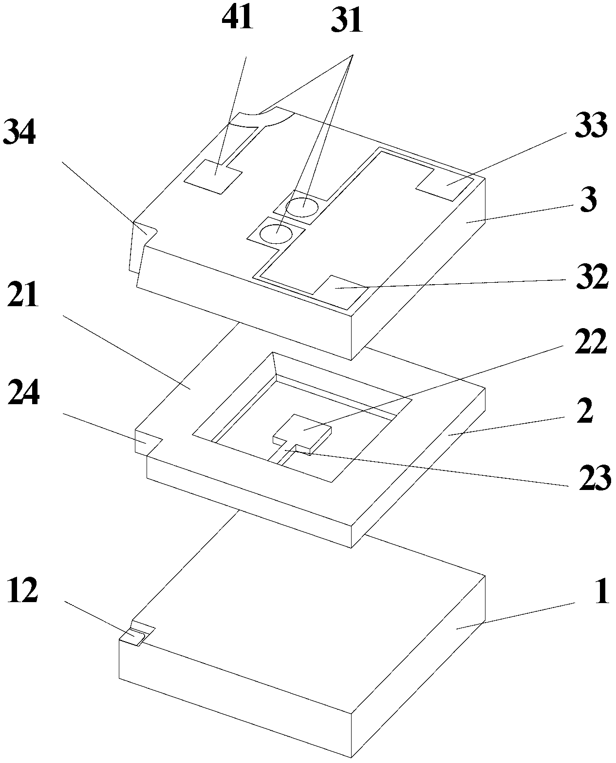
[0034] see Figure 1-7 , the pressure sensor described in the embodiment of the present invention is provided with a pressure sensitive layer 1, a cantilever resonant layer 2, a vacuum package cover layer 3 and electrodes; the pressure sensitive layer 1, a cantilever resonator layer 2 and a vacuum package cover layer 3 are arranged from bottom to top . A pressure sensitive film 11 is provided in the middle of the pressure sensitive layer 1 , and the upper end of the pressure sensitive layer 1 is connected to the lower end of the cantilever resonant layer 2 . The cantilever resonant layer 2 is a frame structure, and the cantilever resonant layer 2 is provided with a cantilever beam 22 with a mass block 23, and the cantilever beam 22 with the mass block 23 extends from the inner side of the frame of the cantilever resonant layer to the center, and the cantilever beam The mass block 23 of 22 is located right above the pressure sensitive membrane 11; The electrodes include a dri...


PUM


Abstract

The invention discloses a pressure sensor utilizing electrostatic negative stiffness and a production method of the pressure sensor. The pressure sensor comprises a pressure-sensitive layer, a cantilever-type resonance layer, a vacuum-sealed cover layer and electrodes from bottom to top. The production method includes taking photoresist as a mask to process an electrode hole and a lead gap on a glass sheet, and connecting the electrode hole and the lead gap with a silicon wafer to etch out a drive silicon electrode and a detect silicon electrode; reserving a mask window in a metal mask or a silicon oxide prior to etching out blind grooves both on the top and bottom surfaces of the cantilever-type resonance layer; etching out the lead gap of the cantilever-type resonance layer and a cantilever beam with a mass; taking the silicon oxide layer and a silicon nitride layer as masks to etch out a pressure-sensitive film and a grounding electrode which are single-sided to produce the pressure-sensitive layer; connecting both the upper end and the lower end of the cantilever-type resonance layer to form a combined piece prior to connecting with the vacuum-sealed cover layer to form a three-layer combined piece; mounting the three-layer combined piece to a hard board jig; producing a metal layer covering the grounding electrode and a lead electrode of the drive silicon electrode by means of spurting and evaporating so as to form the sensor finally.

Description

technical field [0001] The invention relates to a pressure sensor, in particular to a pressure sensor utilizing electrostatic negative stiffness and a manufacturing method thereof. Background technique [0002] The silicon microresonant pressure sensor based on micro-electromechanical (MEMS) technology is currently the most accurate silicon micro-pressure sensor. It indirectly measures the pressure by detecting the change of the natural frequency of the microstructure, and outputs a quasi-digital signal. It can be directly connected to the computer. It is also easy to form an instrument that directly displays numbers. The accuracy of the silicon microresonant sensor is mainly affected by the mechanical characteristics of the vibrating structure, so it has a strong ability to resist electronic interference and stable performance. In addition, silicon microresonant pressure sensors also have many advantages such as fast response, wide frequency range, low power consumption, c...

Claims


Application Information

Patent Timeline
IPC IPC(8): G01L1/10G01L9/00
Inventor 孙道恒杜晓辉王凌云蔡建法王小萍
Owner XIAMEN UNIV
Why Eureka
Try Eureka