
Numerical-controlled high-speed drilling and milling device

A drilling and milling, high-speed technology, applied in the field of CNC high-speed drilling and milling devices, can solve the problems that the processing device cannot adapt to the market demand, the feed speed and the tool change speed are slow, etc., to reduce the auxiliary processing time, optimize the structure, and improve the workmanship. Effect

Inactive Publication Date: 2013-08-14
上海莱必泰精密机电有限公司
View PDF6 Cites 9 Cited by
  • Summary
  • Abstract
  • Description
  • Claims
  • Application Information

AI Technical Summary

Problems solved by technology

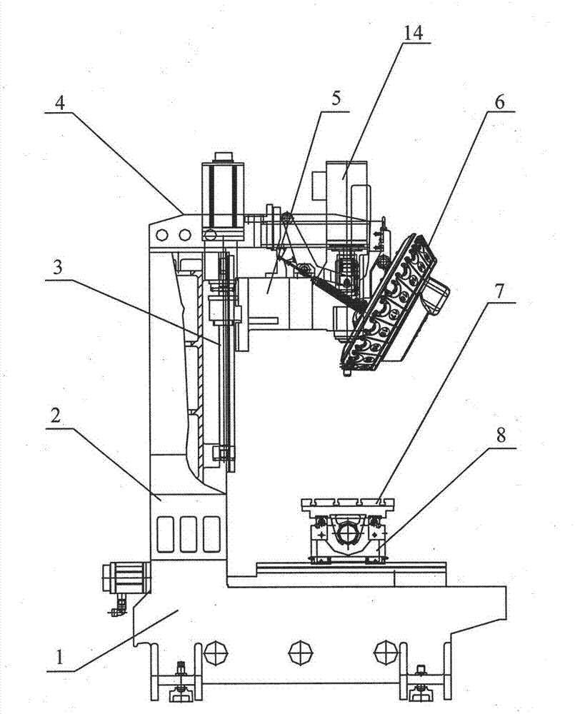
[0002] Traditional CNC machining devices are mainly used for the processing of castings and steel parts. The relative characteristics are that the machine tool has relatively high rigidity, relatively accurate motion accuracy, and relatively large spindle power, but the feed speed and tool change speed are relatively slow, but they can basically meet Processing of general parts
[0003] With the rapid development of consumer electronics in recent years, the market competition has become more and more serious, so new requirements have been put forward for the manufacturing time and precision of consumer electronics parts. Traditional processing devices can no longer meet the market demand.

Method used


Image

  • Numerical-controlled high-speed drilling and milling device
  • Numerical-controlled high-speed drilling and milling device
  • Numerical-controlled high-speed drilling and milling device

Examples


Embodiment Construction

[0012] A preferred embodiment will be given below, and the present invention will be described more clearly and completely in conjunction with the accompanying drawings.

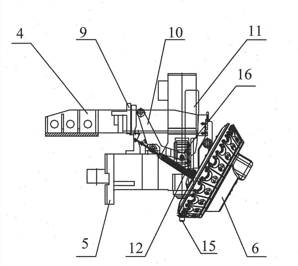
[0013] Such as figure 1 As shown, the CNC high-speed drilling and milling device of the present invention includes a bed 1, a column 2, a ball screw 3, a tool magazine support 4, a spindle box 5, a tool magazine 6, a workbench 7, and a carriage 8, and the column 2 is fixed on the bed 1, the ball screw 3 is located on one side of the column 2, the tool magazine bracket 4 is fixed on the column 2, the spindle box 5 is fixed under the tool magazine bracket 4, the tool magazine 6 is connected with the tool magazine bracket 4, the workbench 7, drag The board 8 is provided on the bed 1 .

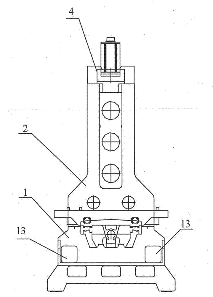
[0014] Among them, bed 1, column 2, headstock 5, workbench 7 and carriage 8 are all integrally cast by HT250 gray cast iron. The shape of column 2 is herringbone (see figure 2 ), which strengthens the strength and stability ...


PUM


Abstract

The invention discloses a numerical-controlled high-speed drilling and milling device comprising a lathe bed, a stand column, a ball screw rod, a tool changer support, a spindle box, a tool changer, a workbench and a carriage. The stand column is fixed on the lathe bed, the ball screw rod is positioned on one side of the stand column, the tool changer support is fixed on the stand column, the spindle box is fixed below the tool changer support, the tool changer is connected with the tool changer support, and the workbench and the carriage are arranged on the lathe bed. The numerical-controlled high-speed drilling and milling device has an optimized structure, production efficiency can be improved and production cost can be greatly reduced.

Description

technical field [0001] The invention relates to a drilling and milling device, in particular to a numerically controlled high-speed drilling and milling device. Background technique [0002] Traditional CNC machining devices are mainly used for the machining of castings and steel parts. The relative characteristics are that the machine tool has relatively high rigidity, relatively accurate motion accuracy, and relatively large spindle power, but the feed speed and tool change speed are relatively slow, but they can basically meet the requirements. Processing of general parts. [0003] With the rapid development of consumer electronics in recent years, market competition has become more and more serious, so new requirements have been put forward for the manufacturing time and precision of consumer electronics parts, and traditional processing devices can no longer meet market demand. Contents of the invention [0004] The technical problem to be solved by the present inven...

Claims


Application Information

Patent Timeline
Patent Type & Authority Applications(China)
IPC IPC(8): B23P23/02B23Q1/01B23Q3/155
Inventor 沈雨秦丹辉
Owner 上海莱必泰精密机电有限公司
Learn More