
Automatic wire welding process and automatic wire welding machine

An automatic welding machine, automatic welding technology, applied in welding equipment, welding equipment, connection and other directions, can solve the problems of easy breaking and falling off, irregular shape, waste of manpower and material resources, etc. Beautiful appearance and the effect of improving product quality

Active Publication Date: 2013-08-21
东莞市恒仓智能机械设备厂
View PDF10 Cites 20 Cited by
  • Summary
  • Abstract
  • Description
  • Claims
  • Application Information

AI Technical Summary

Problems solved by technology

[0002] The traditional wire welding directly welds the tin wire to the solder joint between the wire and the connecting terminal. The solder joint is not firmly connected, which is likely to cause short circuit or short circuit and other faults, which affects the normal use of the wire terminal. The tin wire cannot completely cover the wire end during soldering, which is easy Breaks and falls off, doesn't last long
Directly using ordinary tin wire will cause uneven melting of tin at the soldering point, and the shape is irregular, which will affect the appearance
[0003] The integration of feeding materials to finished products requires automatic energy control. Traditional welding mostly uses manual or semi-automatic step-by-step welding, resulting in a lot of waste of manpower and material resources, and the work efficiency is not high, and the product quality is uneven, which affects product quality.

Method used


Image

  • Automatic wire welding process and automatic wire welding machine
  • Automatic wire welding process and automatic wire welding machine
  • Automatic wire welding process and automatic wire welding machine

Examples


Embodiment

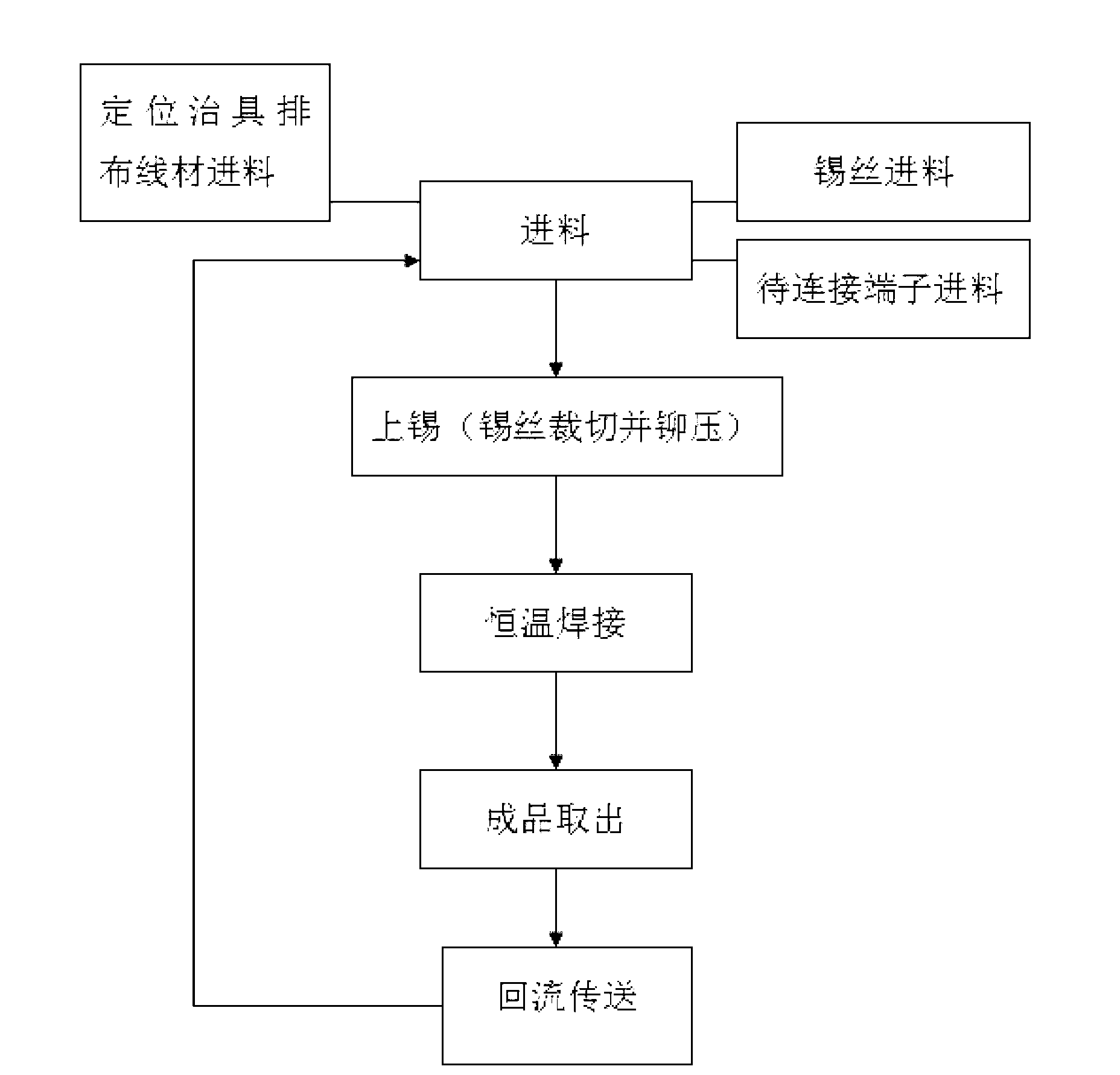
[0028] Such as image 3 and Figure 4 As shown, the wire rod automatic welding process in the present embodiment comprises the following steps:

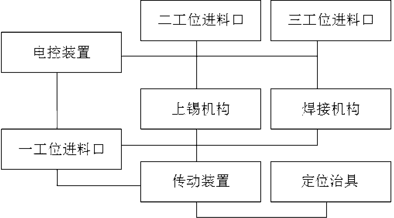
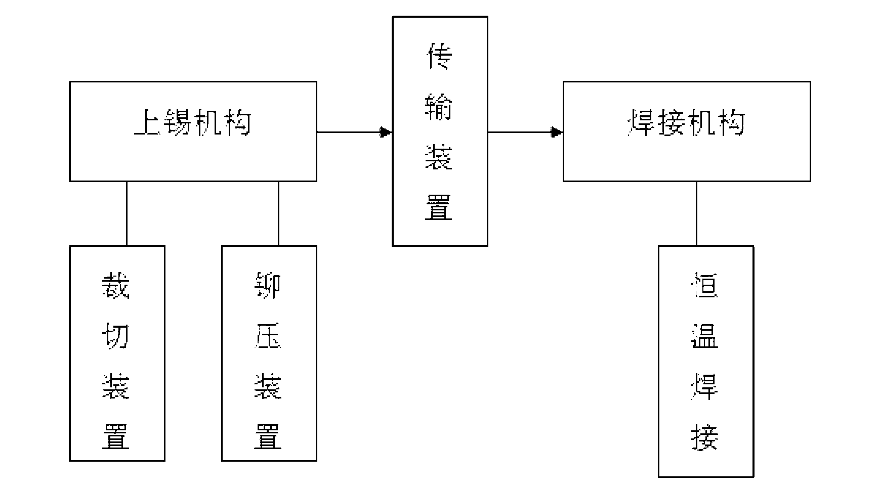
[0029] (1) Set up a mechanical main body, the main body is equipped with a transmission device and a welding device, and the welding device is respectively equipped with a feeding processing device, a tinning mechanism, a welding mechanism and a station exit; the feeding device is respectively equipped with a The wire material inlet of the station, the tin wire inlet of the second station, and the terminal inlet of the third station, the transmission device is respectively provided with one or more sets of positioning fixtures, and the wire material inlet of the first station is The rear row is equipped with a peeling and cutting mechanism.

[0030] (2) Feed material processing: The feed port of the first station of the feed processing device guides the wire to be welded to the positioning jig pushed by the transmission device afte...


PUM


Abstract

The invention discloses an automatic wire welding process. A first station feed inlet of a feed processing device guides a to-be-welded wire which is subjected to peeling and cutting at a cutting station into a positioning jig of a transmission device. A second station feed inlet guide a tin wire into a tinning mechanism. A third station feed inlet guide a to-be-connected terminal into a welding structure. The tinning mechanism flattens and cuts the tin wire to form a tin sheet, and the tin sheet is riveted by means of casting and wrapped at the connection of the wire and the terminal. The welding structure guides the positioning jig for fixing the to-be-welded wire to a welding station and performs constant-temperature welding of the wire and the terminal after accurate positioning of the wire and the to-be-connected terminal. By the automatic wire welding process, automatic wire welding is achieved, tin wire welding totally covers wire heads, crack and dropping are less easily, and product service life is prolonged. The invention further provides an automatic wire welding machine for realizing the process.

Description

technical field [0001] The invention relates to an automatic wire welding technology, in particular to an automatic wire welding process, and more particularly to an automatic wire welding machine for realizing the process. Background technique [0002] The traditional wire welding directly welds the tin wire to the solder joint between the wire and the connecting terminal. The solder joint is not firmly connected, which is likely to cause short circuit or short circuit and other faults, which affects the normal use of the wire terminal. The tin wire cannot completely cover the wire end during soldering, which is easy Breaks and falls off and doesn't last long. Direct use of ordinary tin wire will cause uneven melting of solder joints and irregular shape, which will affect the appearance. [0003] The integration of feeding materials to finished products requires automatic energy control. Traditional welding mostly uses manual or semi-automatic step-by-step welding, resulti...

Claims


Application Information

Patent Timeline
Patent Type & Authority Applications(China)
IPC IPC(8): B23K3/00B23K3/06B23K3/08H01R43/02
CPCH01R43/02B23K31/02H01R43/0235B23K1/0016B23K3/0607B23K3/08B23K2101/32B23K2101/38
Inventor 辜国彪
Owner 东莞市恒仓智能机械设备厂
Learn More