Plastic bottleneck excess material detecting method and device based on machine vision

A technology of machine vision and detection method, which is applied in the direction of optical detection of defects/defects, etc., can solve the problems of separation of bottle mouth internal information and bottle body background information, damage to filling equipment, and limit detection speed, etc., to achieve low machine performance requirements and reduce The space occupied by the equipment and the effect of avoiding misjudgment

Inactive Publication Date: 2013-08-21
SOUTH CHINA UNIV OF TECH
View PDF7 Cites 18 Cited by
  • Summary
  • Abstract
  • Description
  • Claims
  • Application Information

AI Technical Summary

Problems solved by technology

The remaining material in the bottle mouth will reduce the inner area of ​​the bottle mouth, causing the liquid to flow out or damage the filling equipment when the liquid is poured into the bottle. Therefore, plastic bottles with residual material defects must be removed from the production line
The traditional imaging method is not conducive to the separation of the internal information of the bottle mouth and the background information of the bottle body. The general processing method is to find the edge of the bottle mouth, then fit the inner and outer circles of the bottle mouth, and then judge the gray value of the image inside the circle. The process is cumbersome and limited. The detection speed may even cause misjudgment due to inaccurate lighting or positioning

Method used


Image

  • Plastic bottleneck excess material detecting method and device based on machine vision
  • Plastic bottleneck excess material detecting method and device based on machine vision
  • Plastic bottleneck excess material detecting method and device based on machine vision

Examples


Embodiment

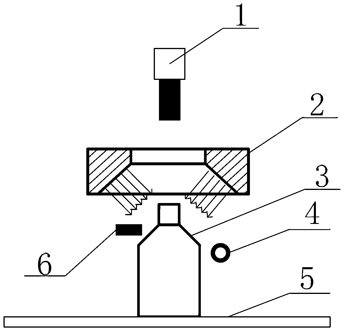
[0028] Such as figure 1 , figure 2 , image 3 shown. The machine vision-based detection device for remaining material at the mouth of a plastic bottle of the present invention includes a computer system (not shown in the figure), one for taking pictures of the bottle mouth image and putting it into an imaging unit, one for processing the bottle mouth image and A processing unit for defect identification, and a rejecting unit for rejecting plastic bottles 3 with residual material in the mouth of the bottle.

[0029] The imaging unit includes a position sensor 6, a light source 2, a camera 1, and a light source controller (not shown in the figure). The camera 1, the light source 2 and the mouth of the plastic bottle are on the same vertical line. The position sensor 6 transmits the signal to the light source controller and the camera 1 to trigger the light source 2 to light up and the camera 1 to take pictures. The light source uses ring light. Adjust the distance between c...


PUM


Abstract

The invention discloses a plastic bottleneck excess material detecting method and device based on machine vision. Detection objects are semitransparent and nontransparent plastic bottle products formed by hollow blow molding, and a detection defect type is excess materials in bottlenecks. The method comprises the following steps of: conveying molded plastic bottles to a detection station by a conveying device, and lighting up light sources through a position sensor, and triggering cameras to photograph; establishing an imaging system according to appropriate light sources, cameras and distances between the light sources and the plastic bottles and between the cameras and the plastic bottles, wherein the image effect only highlights details in the bottlenecks and shields the interference of other details; transmitting images to a computer, and determining whether excess materials are in the bottles through image processing software; and removing bottles with excess materials, and recording the removed bottles. According to the invention, whether excess materials exist in plastic bottlenecks can be detected rapidly and accurately on line; and the plastic bottleneck excess material detecting method and device based on machine vision have the characteristics that the imaging scheme can highlight details in bottlenecks, so that the subsequent image processing method is simple, the computation is less, and moreover, the whole detection system is high in stability.

Description

technical field [0001] The invention relates to the field of machine vision automatic detection, in particular to a machine vision-based method and device for detecting residual material at the mouth of a plastic bottle. Background technique [0002] After decades of development, machine vision technology has become a research hotspot in the field of industrial automation. Machine vision is applied to product defect detection. Its advantages are high efficiency, stability, rapid identification of defects and no fatigue due to long working hours compared with manual detection. It can greatly liberate human labor and improve the level of production automation. [0003] One of the most critical aspects of a machine vision system is choosing the right imaging solution. Through the appropriate light source lighting scheme, the difficulty of image processing algorithm segmentation and recognition can be greatly reduced, and the positioning and measurement accuracy of the system c...

Claims


Application Information

Patent Timeline
Patent Type & Authority Applications(China)
IPC IPC(8): G01N21/89
Inventor 文生平李雪烽
Owner SOUTH CHINA UNIV OF TECH
Why Eureka
Try Eureka