
Parallel optical transceiver components for broadband high-speed transmission

A technology of optical transceiver components and high-speed transmission, applied in the coupling of optical waveguides, etc., can solve the problems of complex packaging structure, difficult processing, long process time, etc., to reduce processing costs, reduce mounting accuracy and high coupling efficiency Effect

Active Publication Date: 2015-08-12
INNOLIGHT TECH (TONGLING) LTD
View PDF16 Cites 0 Cited by
  • Summary
  • Abstract
  • Description
  • Claims
  • Application Information

AI Technical Summary

Problems solved by technology

The packaging structure is complex, the processing is difficult, the process time is long, and the cost is high

Method used


Image

  • Parallel optical transceiver components for broadband high-speed transmission
  • Parallel optical transceiver components for broadband high-speed transmission
  • Parallel optical transceiver components for broadband high-speed transmission

Examples


Embodiment Construction

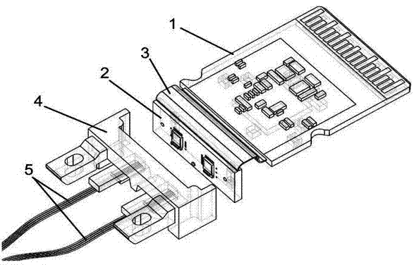
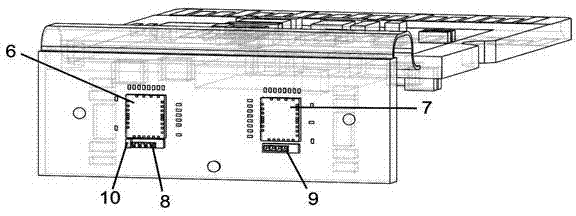
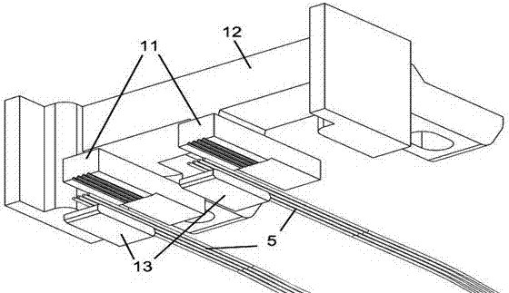
[0017] Such as figure 1 As shown, the parallel optical transceiver assembly for broadband high-speed transmission includes a first printed circuit board 1, a second printed circuit board 2, a flexible board 3 connecting the first printed circuit board 1 and the second printed circuit board 2, and a TIA Transimpedance amplifier 6, laser driver chip 7, PD photodetector array 8, VCSEL vertical cavity emitting laser array 9, optical fiber array 5 and optical fiber fixing assembly 4; one end of the first printed circuit board 1 forms a signal of a gold-plated board structure input ports such as figure 2 As shown, the surface of the second printed circuit board 2 is packaged with a TIA transimpedance amplifier 6, a laser driver chip 7, a PD photodetector array 8, and a VCSEL vertical cavity emitting laser array 9 through gold wire bonding, and the front end of the optical fiber array 5 is placed on the optical fiber In the fixed assembly 4, the optical fiber array 5 is coupled and...


PUM


Abstract

The invention relates to a parallel light transmitting and receiving assembly for broadband high-speed transmission. A signal input port is formed at one end of a first printed circuit board, a trans-impedance amplifier (TIA), a laser driving chip, a photoelectric detector (PD) array and a VCSEL perpendicular cavity transmitting laser array are packaged on the surface of a second printed circuit board, the front end of an optical fiber array is placed in an optical fiber fixing assembly, the optical fiber array aligns at the PD array in a coupling mode, and the optical fiber array aligns at the VCSEL perpendicular cavity transmitting laser array in a coupling mode. The optical fiber fixing assembly comprises a base, an optical fiber orientation conversion piece base plate and a covering plate, slant steps are arranged on the surface of the optical fiber orientation conversion piece base plate, a V-shaped groove is carved in an upper step, a lower step is a plane, bare fibers of an optical fiber array are placed in the V-shaped groove, the covering plate covers the V-shaped groove, and the optical fiber orientation conversion piece base plate, the covering plate and the base are connected through fixing glue. The technology combining a soft plate and the hard plate is adopted, and optical coupling is carried out on the VCSEL perpendicular cavity transmitting laser array and the PD photoelectric detector array by the driving aligning technology.

Description

technical field [0001] The invention relates to a parallel optical transceiver assembly for broadband high-speed transmission, in particular to a parallel optical transceiver assembly for broadband high-speed transmission and an optical fiber fixing part thereof. Background technique [0002] With the improvement of high-speed signal transmission requirements, parallel optical transceiver components emerged as the times require. The parallel optical module is to realize the mutual conversion of multiple electrical signals and optical signals in a single structure, so as to realize the function of sending and receiving. Due to the high bandwidth density and low power consumption brought about by device integration and miniaturization, the transmission bandwidth and power consumption of the parallel optical module are much better than multiple discrete devices, thereby improving the transmission performance of the system. [0003] However, the existence of multiple discrete c...

Claims


Application Information

Patent Timeline
Patent Type & Authority Patents(China)
IPC IPC(8): G02B6/43G02B6/42
Inventor 李伟龙陈龙孙雨舟王祥忠刘圣
Owner INNOLIGHT TECH (TONGLING) LTD
Learn More