Device for promoting reaction by direct contact between blast furnace slag particles and biomass particles

A biomass particle, contact reaction technology, applied in the direction of biofuel, direct heating dry distillation, coke oven, etc., can solve the problems of different particle specific gravity, different residence time, low efficiency, etc., to solve pollution, avoid environmental pollution, easy to operate Effect

Inactive Publication Date: 2013-08-28
CHONGQING UNIV
View PDF1 Cites 9 Cited by
  • Summary
  • Abstract
  • Description
  • Claims
  • Application Information

AI Technical Summary

Problems solved by technology

At present, the device used to study the reaction between biomass and blast furnace slag particles in the laboratory mainly heats the biomass through heat convection and heat radiation to achieve the purpose of pyrolysis. Different lead to different residence time and difficult to achieve
[0007] As a large agricultural country in my country, there is a serious waste of resources in agricultural production, such as biological straw. Many rural areas use burning to obtain energy. This method is not only inefficient but also pollutes the environment.
At present, in domestic and foreign research on biomass application, there are no more than three technical methods: physics, chemistry and biological transformation.

Method used


Image

  • Device for promoting reaction by direct contact between blast furnace slag particles and biomass particles
  • Device for promoting reaction by direct contact between blast furnace slag particles and biomass particles
  • Device for promoting reaction by direct contact between blast furnace slag particles and biomass particles

Examples


Embodiment Construction

[0042] The present invention will be described in further detail below with reference to the accompanying drawings.

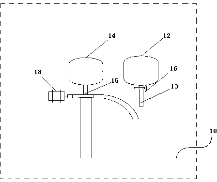
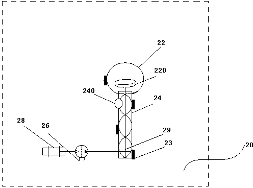
[0043] A device for direct contact reaction between blast furnace slag particles and biomass particles, mainly including a feeding device 10, a reaction device 20, a separation device 30, and a gas purification and collection device 40; the gas purification and collection device 40 includes a tar gas separation device connected in sequence at the top device 42, a carbon dioxide filter bottle 44 and a gas storage tank 46, and the top of the tar gas separator 42 communicates with the gas outlet of the reaction device 20.

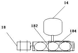
[0044] The feeding device 10 has a feeding device discharge pipe, and the feeding device 10 includes a biomass particle feeder 14, a blast furnace slag particle feeder 12 and a stepping motor 18; the biomass particle feeder 14 has a "D"-shaped biomass particle feeder Pipe 15, one end of the biomass particle feeding pipe 15 is connected with the...


PUM

PropertyMeasurementUnit
diameteraaaaaaaaaa
diameteraaaaaaaaaa
heightaaaaaaaaaa

Abstract

The invention relates to a device for promoting reaction by direct contact between blast furnace slag particles and biomass particles. The device comprises a feeding device, a reaction device, a separation device and a gas purification and collection device, wherein the feeding device is provided with a discharge pipe of the feeding device; the bottom of the reaction device is provided with a discharge hole of the reaction device, and the top of the reaction device is provided with an air outlet and a feeding hole of the reaction device; the separation device is provided with a slag outlet, and the top of the separation device is also provided with a feeding hole of the separation device; the discharge pipe of the feeding device is communicated with the feeding hole on the top of the reaction device; the discharge hole at the bottom of the reaction device is communicated with the feeding hole on the top of the separation device; and the air outlet on the top of the reaction device is communicated with the gas purification and collection device. The device can be used for promoting gas production of biomass pyrolysis by the high temperature provided by the collision between the blast furnace slag particles and the biomass particles in the reaction device; and finally, the mixed particles are separated, the separated blast furnace slag particles can be taken as building materials, and the separated biomass particles can be taken as carbon fuel, so that the device is energy-saving and environment-friendly.

Description

technical field [0001] The invention belongs to the technical field of metallurgical engineering and energy recovery, and relates to a device for direct contact reaction between blast furnace slag particles and biomass particles. [0002] Background technique [0003] The iron and steel industry is an important basic industry for the development of my country's national economy. China's iron and steel industry has developed rapidly since the 1990s. In 2012, the crude steel output reached 716 million tons, accounting for about 46.3% of the world's crude steel output. pivotal role. The rapid growth of steel production brings more and more solid waste. In 2010, the total amount of solid waste generated by China's iron and steel industry was about 380 million tons, and in 2011 it reached 430 million tons, an increase of 13.2%. Among the solid waste, blast furnace slag accounts for a large proportion, accounting for about 59.5% in 2012. Blast furnace slag contains a lot of hea...

Claims


Application Information

Patent Timeline
Patent Type & Authority Applications(China)
IPC IPC(8): C10B53/02C10B49/16
CPCY02E50/10
Inventor 郭福亮吕学伟秦跃林尹续臣严志明杨照
Owner CHONGQING UNIV
Why Eureka
Try Eureka