Method for continuously measuring temperature of molten metal

A technology of molten metal and temperature measuring element, which is applied in the field of continuous measurement of molten metal temperature, can solve the problems of no widely applicable correspondence, inability to realize continuous measurement of molten steel, and difficulty in compensating for wire connection, etc., and achieves convenient measurement and measurement cost. Low, easy-to-achieve effects

Inactive Publication Date: 2013-09-04
沈阳东大高温材料有限公司
View PDF2 Cites 1 Cited by
  • Summary
  • Abstract
  • Description
  • Claims
  • Application Information

AI Technical Summary

Problems solved by technology

There is no generally accepted correspondence between the electromotive force generated at each temperature and the temperature of the working end;
[0010] (2) Zirconium diboride + molybdenum and zirconium diboride + tungsten are hard materials, not easy to sinter and prepare, and not easy to connect with compensation wires;
[0011] (3) When embedded in the ladle lining, since the lining refractory material is non-conductive, no loop can be formed between the two electrode materials, therefore, continuous measurement of molten steel cannot be realized

Method used


Image

  • Method for continuously measuring temperature of molten metal
  • Method for continuously measuring temperature of molten metal
  • Method for continuously measuring temperature of molten metal

Examples


Embodiment 1

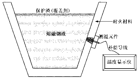
[0024] After the continuous casting tundish refractory material masonry is completed, press figure 2 In the shown assembly method, a fixed temperature measuring element is installed on the tundish, and the casting operation is performed after high-temperature baking. During the casting process, use the compensation wire to connect the temperature measuring element and the temperature display instrument, and measure the temperature change range of the molten steel in real time from 1560°C to 1570°C. For comparison, during the casting process, a standard thermocouple protected by a corundum tube was inserted into the molten steel from the upper part of the tundish to measure the temperature of the molten steel every half an hour. Compared with the temperature obtained by the temperature measuring device of the present invention, the temperature difference is ±2°C.

Embodiment 2

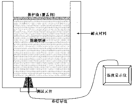
[0026] After the ladle refractory masonry is completed, press image 3 In the shown assembly method, a fixed temperature measuring element is installed on the ladle, and the refining operation is carried out after high-temperature baking. During the refining process, the temperature measuring element is connected with the temperature display instrument by using the compensation wire, and the temperature range of the molten steel in the ladle is measured in real time to be 1580°C-1610°C. For comparison, a standard thermocouple protected by a corundum tube was inserted into the molten steel from the upper part of the ladle to measure the temperature of the molten steel every half an hour. Compared with the temperature obtained by the temperature measuring device of the present invention, the temperature difference is ±2°C.


PUM


Abstract

The invention provides a method for continuously measuring the temperature of molten metal, and belongs to the technical field of measurement and detection. A measuring structure adopted in the method comprises three parts including a temperature measuring element, a display instrument and a compensation conducting wire, wherein the temperature measuring element is formed by two platinum-rhodium conducting wires which are buried in fire-resistance materials and the ends of which are exposed out, the display instrument is used for displaying the temperature of the molten metal in real time, and the compensation conducting wire is connected with the temperature measuring element and the temperature display instrument. Before the measurement, the temperature measuring element is fastened at the side wall or the bottom of a container for containing molten metal, and the two exposed platinum-rhodium conducting wires and the molten metal are enabled to form a thermocouple loop in the measurement process, so the continuous and precise measurement on the temperature of the molten metal can be realized.

Description

technical field [0001] The invention belongs to the technical field of measurement and detection, in particular to a method for continuously measuring the temperature of molten metal. Background technique [0002] Continuous real-time measurement of molten metal temperature is of great significance for accurately grasping the temperature change of molten metal, timely adjusting the smelting process, and accurately controlling the smelting process. For example, ladle refining and tundish casting etc. [0003] At present, the main methods for continuous measurement of molten metal temperature are: [0004] (1) Black body cavity method: Insert the temperature measuring tube into the molten metal, the radiation wave emitted by the temperature measuring tube is accepted by the infrared detector and converted into the temperature of the molten metal; [0005] (2) Optical imaging method: Insert the temperature measuring tube body into the molten metal, and then use the optical sy...

Claims


Application Information

Patent Timeline
Patent Type & Authority Applications(China)
IPC IPC(8): G01K7/02
Inventor 于景坤戴文斌
Owner 沈阳东大高温材料有限公司
Why Eureka
Try Eureka