Millimeter wave micropore coupler for measuring high power

A pinhole coupling, millimeter wave technology, applied in waveguide-type devices, electrical components, connecting devices, etc., can solve problems such as inability to measure high-power microwaves

Inactive Publication Date: 2013-09-04
UNIV OF ELECTRONIC SCI & TECH OF CHINA
View PDF4 Cites 14 Cited by
  • Summary
  • Abstract
  • Description
  • Claims
  • Application Information

AI Technical Summary

Problems solved by technology

Since the general power measuring instruments are of low power,

Method used


Image

  • Millimeter wave micropore coupler for measuring high power
  • Millimeter wave micropore coupler for measuring high power
  • Millimeter wave micropore coupler for measuring high power

Examples


Embodiment 1

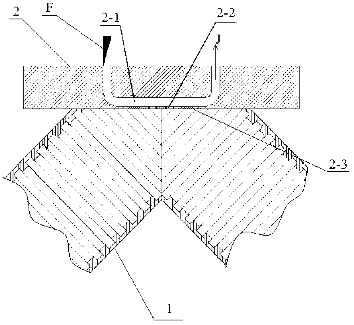
[0015]This embodiment takes the small hole coupler used for measuring the transmission power of the ECRH (electron cyclotron resonance heating) system corrugated waveguide transmission line with an inner diameter of φ63.5mm and a material of 6061-T6 aluminum alloy as an example: Among them, the inner diameter of the corrugated waveguide transmission line 1 is φ63. 5mm, the depth of each corrugated groove is 0.41mm, the groove width is 0.46mm, the period is 0.66mm, and the outer diameter is φ76.2mm. 2 (that is, the ratio of the area of ​​the ring mouth to the cross-sectional area of ​​the corrugated waveguide cavity is 1.29), the cut plane and the center line of the transmission line on both sides of the elbow are at an angle of 45° and perpendicular to the plane formed by the two center lines; the coupler body 2 The thickness is 11.48mm, the radius size is 61.40mm, and the "U"-shaped waveguide 2-1 adopts the R1400 standard rectangular waveguide size, that is, the nominal width ...

Embodiment 2

[0018] In this embodiment, a coupling hole 2-2 is opened at the center of the reflection surface 2-3 as a coupling channel between the bottom section of the "U" shape waveguide 2-1 and the right-angle elbow on the corrugated waveguide transmission line 1. Take a coupler connected to the inner cavity as an example. The two coupling holes 2-2 are symmetrically distributed along the length direction of the bottom section of the "U" waveguide with the center of the mirror as the reference. The height (depth) of each hole is 0.3mm, and the radius is R0.23mm. The hole pitch is 0.75mm, and the rest are the same as in Example 1.

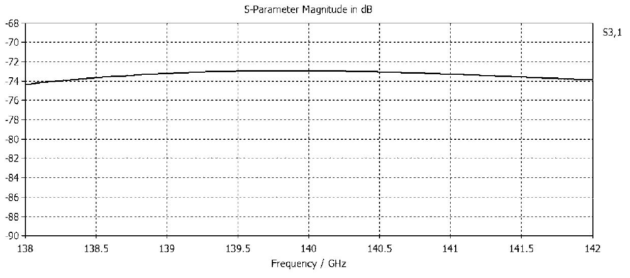
[0019] The coupler of this embodiment has been simulated (the system transmission parameters are the same as those in Embodiment 1), image 3 The upper part shows the coupling coefficient (S31) curve, ranging from -72.14dB (138.05GHz) to -70.86dB (139.78GHz); the lower part shows the isolation (S41) curve, ranging from -89.18dB (138.05 GHz)—-105.08dB (140.8...


PUM

PropertyMeasurementUnit
Radiusaaaaaaaaaa
Thicknessaaaaaaaaaa

Abstract

The invention provides a millimeter wave micropore coupler for measuring high power in the technology of heating nuclear fusion plasma large-power radio frequency wave. The millimeter wave micropore coupler comprises a coupler body of which the material is copper alloy or copper matrix composite and is provided with a reflecting surface, an input section and an output section which are arranged in the body, comprise base sections and are positioned at the two ends of the base section, a corrugated waveguide transmission line square bend which is integrally connected with the reflecting surface of the coupler, and a coupling hole which is used for communicating the base section of U-shaped waveguide with the inner cavity of the corrugated waveguide transmission line square bend. The millimeter wave micropore coupler is simple in structure, large in power capacity, little in insertion loss, flexible and convenient to use, and high in reliability; during measuring process, due to the power coupling method, the influence of the external environment on the measuring result can be avoided; and the millimeter wave micropore coupler has outstanding advantages on the aspect of measuring the millimeter wave band high power microwave, and can be widely applied to measuring transmission power of an ECRH (electron cyclotron resonance heating) system of which the transmission frequency is 138GHz-142GHz and the transmission power is megawatt.

Description

technical field [0001] The invention belongs to the field of nuclear fusion plasma high-power radio-frequency wave heating technology research and experimentation, and particularly relates to a coupling hole with a diameter φ≤0.25mm, which is used for the ECRH (electron cyclotron resonance heating) system with a transmission frequency of 138GHz-142GHz, transmission Millimeter-wave pinhole directional coupler for power measurement on transmission lines in the megawatt range. Background technique [0002] In the ECRH system, the microwave power is one of the important parameters that characterize the system scale. Through the measurement of the microwave power, parameters such as the output power of the microwave source, the power loss at the mode conversion, and the transmission efficiency of the transmission system can be obtained. The transmission power of the ECRH transmission line has reached mega Watt level. Since the general power measuring instruments are of low power...

Claims


Application Information

Patent Timeline
IPC IPC(8): H01P5/12H01P5/18
Inventor 赵青秦龙刘建卫赵怿哲
Owner UNIV OF ELECTRONIC SCI & TECH OF CHINA
Why Eureka
Try Eureka