
Device and method for elutriation and separation of sludge and treatment and reuse of sewage in through channel

A ditch sludge and sewage treatment technology, applied in water/sludge/sewage treatment, centrifuged water/sewage treatment, sludge treatment, etc., can solve the need for regular maintenance of circulation and lifting pump systems, sewage treatment devices Problems such as large footprint and low separation efficiency achieve the effect of saving running time, reducing floor space and reducing operating costs

Active Publication Date: 2013-09-11
SHANGHAI MUNICIPAL ENG DESIGN INST GRP
View PDF7 Cites 12 Cited by
  • Summary
  • Abstract
  • Description
  • Claims
  • Application Information

AI Technical Summary

Problems solved by technology

[0003] The purpose of the present invention is to provide a device for elutriation and separation of channel sludge and sewage treatment and reuse, which can solve the problem of excessive water consumption, low separation efficiency, and the frequent need for circulation and lifting pump systems in the process of channel sludge elutriation pretreatment The problem of permanent maintenance and the large area occupied by the sewage treatment plant

Method used


Image

  • Device and method for elutriation and separation of sludge and treatment and reuse of sewage in through channel
  • Device and method for elutriation and separation of sludge and treatment and reuse of sewage in through channel
  • Device and method for elutriation and separation of sludge and treatment and reuse of sewage in through channel

Examples


Embodiment Construction

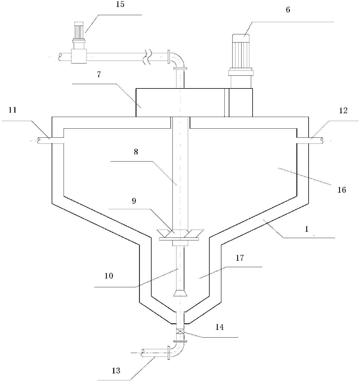
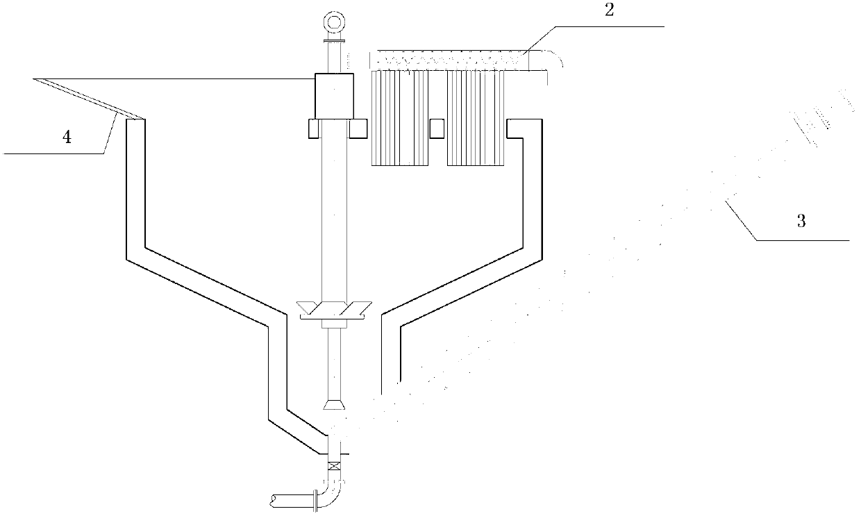
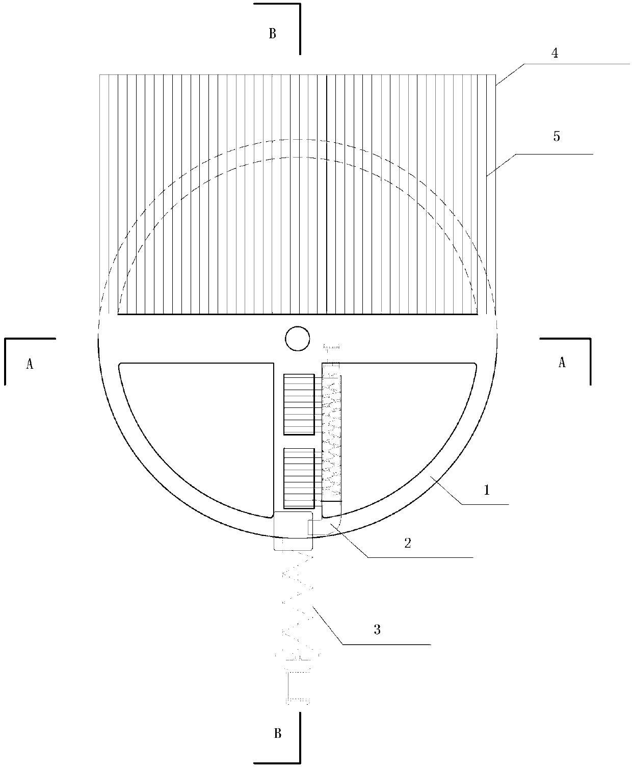
[0012] Such as Figure 2~4 As shown, an integrated device for elutriation and separation of trench sludge and sewage treatment and reuse includes an elutriation separation tank 1, which is characterized in that the elutriation separation tank 1 is composed of a conical elutriation separation chamber 16 (the taper is 2: 1) Composed of conical grit chamber 17 (taper 2:1~1:1), elutriation separation tank 1 is provided with steel platform grid 5, and steel platform grid 5 is provided with a sludge receiving chute 4, The grid spacing of the steel platform grid 5 is 10cm~20cm. The upper part of the elutriation and separation tank 1 is equipped with a slag extraction machine 2, and the upper part of the elutriation separation tank 1 is equipped with a motor 6 with a gearbox. The hollow drive shaft 8 is driven by the transmission gear box 7, and the turntable and the blades 9 are driven to rotate. A dredging pipe 10 is installed in the grit chamber 17. The dredged pipe 10 passes throu...


PUM


Abstract

The invention discloses a device for elutriation and separation of sludge and treatment and reuse of sewage in a through channel. The device is characterized in that an elutriation and separation pool is arranged under a sludge receiving chute and comprises an elutriation and separation chamber and a sand settling chamber positioned below the elutriation and separation chamber; the elutriation and separation chamber is provided with a slag-dredging and pressing integration machine and a stirring device; the stirring device comprises a hollow transmission shaft, a rotary disc and blades; the hollow transmission shaft is positioned in the elutriation and separation chamber; the rotary disc and the blades are arranged on the hollow transmission shaft; a settled sand conveyor is arranged at the bottom of the sand settling chamber; and a mud absorbing pipe is arranged in the sand settling chamber, penetrates through the hollow transmission shaft and is then connected to a sludge treatment facility by a mud discharging pipe. The device disclosed by the invention has the advantages that the problems of overlarge water consumption, low separation efficiency, need of frequent maintenance for a circulating and lifting pump system and large occupied area of a sewage treatment device in the pretreatment of elutriation of sludge in the through channel are solved; and compared with a traditional push-flow separation type separating device, the device disclosed by the invention has the characteristic that the water is saved by more than one time, and the occupied area is saved by about 1 / 2.

Description

technical field [0001] The invention relates to the field of ditch sludge treatment, in particular to a ditch sludge elutriation separation and sewage treatment and reuse device and a treatment and reuse method thereof. Background technique [0002] Ditch sludge is part of the rainwater and sewage that is easily settled during pipeline transportation and gradually accumulates in the pipeline. It is mainly composed of sand, gravel, and a small amount of organic matter. It can be used as an auxiliary raw material for building materials. Waste utilization is carried out, but at the same time, a large amount of heavy metals and pathogenic microorganisms have accumulated in the trench sludge. If not properly treated, it will not only cause secondary pollution of the environment, but also pose a great threat to human health. Compared with the solid matter of channel sludge in western developed countries, which is basically inorganic, the feature of channel sludge in my country is ...

Claims


Application Information

Patent Timeline
IPC IPC(8): C02F11/00C02F1/52
CPCC02F1/38C02F1/5281C02F11/00
Inventor 邹锦林杨姝君陈思谢奎李小林
Owner SHANGHAI MUNICIPAL ENG DESIGN INST GRP
Learn More