
Method and device for measuring low-frequency and small-range vibration signals

A vibration signal and measuring device technology, applied in measuring devices, vibration testing, electrical devices, etc., can solve the problems of frequency compensation circuit failure, reducing vibration signal measurement accuracy, mechanical fatigue, etc., to avoid shortening the service life, overcome the measurement Effects of Signal Failure Problems

Active Publication Date: 2013-09-11
北京中元瑞讯科技有限公司
View PDF4 Cites 35 Cited by
  • Summary
  • Abstract
  • Description
  • Claims
  • Application Information

AI Technical Summary

Problems solved by technology

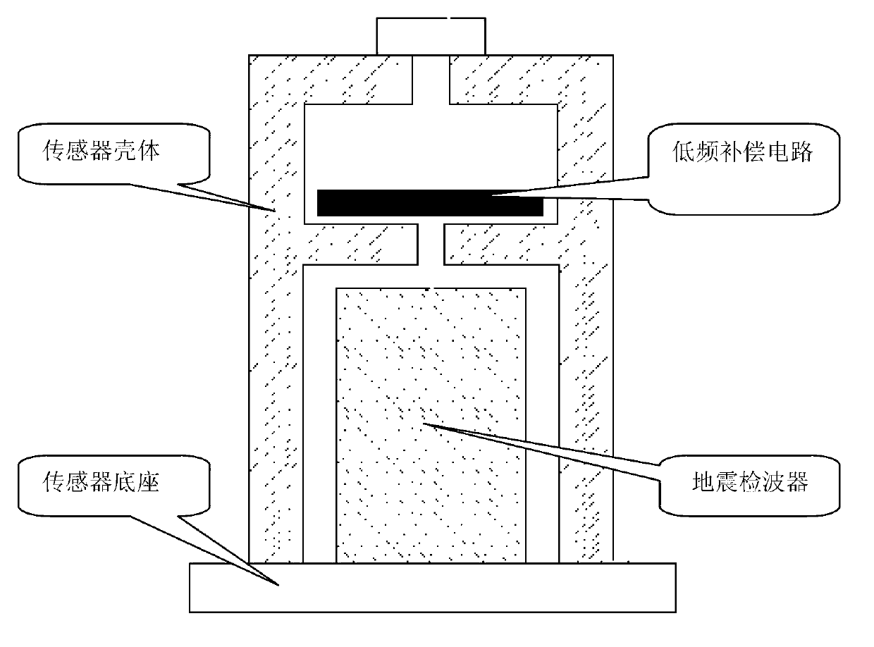
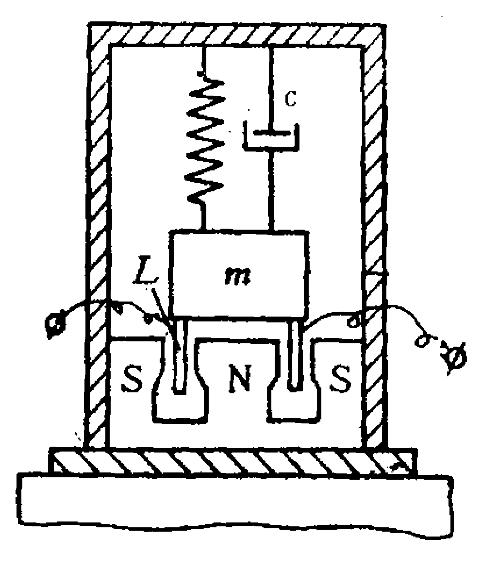
[0007] Since the seismic geophone is equipped with mechanical devices such as inertial mass, coil and spring damping, it is extremely prone to mechanical fatigue and jamming during long-term operation, resulting in the actual measurement of the vibration signal of the measured object and the service life of the sensor. shorten
[0008] 2) Measurement error and frequency compensation circuit failure due to seismic geophone resonance
When the seismic geophone is resonated, the output of the geophone not only cannot guarantee the accuracy of the measurement, but also introduces a vibration signal of a false frequency. At the same time, the resonance signal is amplified by the frequency compensation circuit at the back end, which is extremely easy to cause The failure of the frequency compensation circuit will cause the unreliability of the measurement signal and greatly reduce the measurement accuracy of the vibration signal of the measured object

Method used


Image

  • Method and device for measuring low-frequency and small-range vibration signals
  • Method and device for measuring low-frequency and small-range vibration signals
  • Method and device for measuring low-frequency and small-range vibration signals

Examples


Embodiment 1

[0033] The embodiment of the present invention applies the acceleration sensor to the measurement field of low-frequency and small-amplitude vibration signals for the first time. In the actual acceleration sensor, there is a big problem, that is, the output signal of the acceleration sensor contains a large number of noise signals, which originate from circuit noise, transmission noise and noise caused by piezoelectric crystal installation and manufacturing process. The noise is manifested as the smaller the frequency, the larger the noise. For commonly used accelerometers, the noise below 10Hz is between 5ug√Hz and 10ug√Hz, or even higher.

[0034] The magnification of the integral circuit for integral amplification of the acceleration signal has an inverse relationship with the frequency. The smaller the frequency, the greater the discharge multiple of the signal. When the frequency approaches 0Hz, the magnification is close to infinity. This is the characteristic of the int...

Embodiment 2

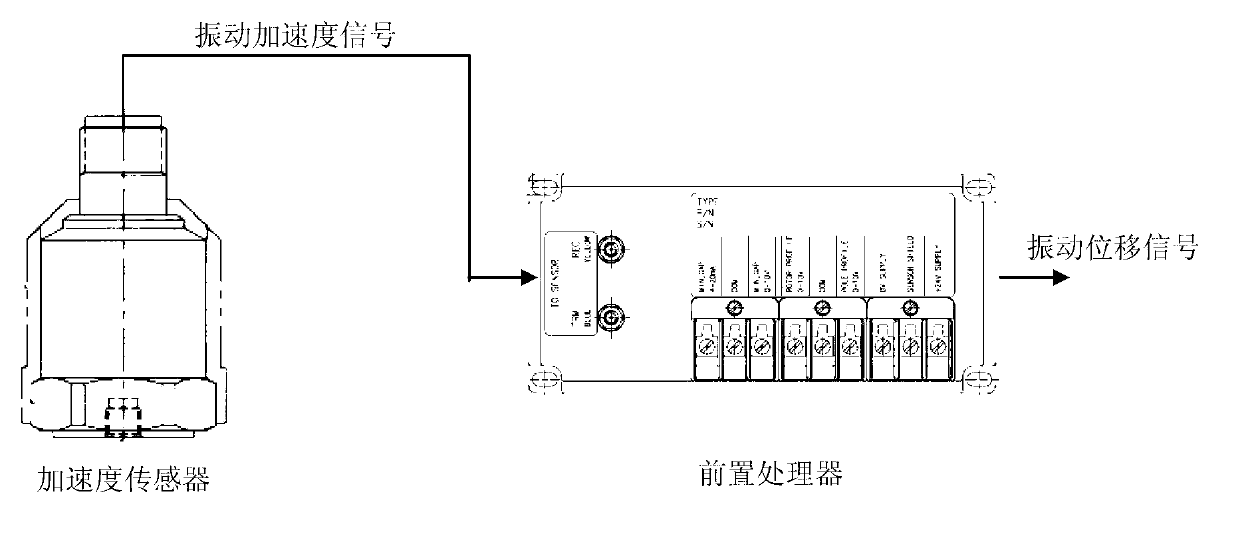
[0072] In this example, the above Figure 4 The second-level analog integral module and subsequent modules in the pre-processor shown are digitally completed by single-chip microcomputer. The specific structure of the above-mentioned pre-processor provided by this embodiment is as follows: Figure 10 As shown, the following modules are included:

[0073] The DC-blocking low-impedance module 101 is used to connect the low-pass module, which is a high-pass filter module, and the high-pass cut-off frequency is designed at 0.5Hz. It is used to receive the vibration acceleration signal output by the acceleration sensor, and perform DC blocking and high-pass filtering processing on the vibration acceleration signal through the RC (resistance-capacitance) circuit, remove the DC signal component in the received vibration acceleration signal, and filter out low frequency Based on the vibration acceleration signal of the set low frequency threshold, the vibration acceleration signal p...

Embodiment 3

[0085] The processing flow of the processing method of a low-frequency, small-amplitude vibration signal measurement method provided by this embodiment is as follows: Figure 11 As shown, the following processing steps are included:

[0086] Step 11, setting the acceleration sensor on the measured object, after the acceleration sensor detects the low-frequency, small-amplitude vibration signal sent by the measured object, convert the low-frequency, small-amplitude vibration signal into a vibration acceleration signal, and convert the vibration Acceleration signal output, the resonant frequency of the acceleration sensor is greater than the maximum effective vibration frequency of the vibration signal sent by the measured object.

[0087] The vibration signal sent by the above-mentioned measured object is a low-frequency, small-amplitude signal. In the embodiment of the present invention, the maximum effective vibration frequency of the vibration signal sent by the above-mentio...


PUM

PropertyMeasurementUnit
Resonant frequencyaaaaaaaaaa
Sensitivityaaaaaaaaaa

Abstract

The invention provides a method and device for measuring low-frequency and small-range vibration signals. The method mainly comprises the steps that an acceleration sensor is arranged on a measured object; after the low-frequency and small-range vibration signals sent by the measured object are detected by the acceleration sensor, the low-frequency and small-range vibration signals are converted to vibration acceleration signals; the integration-amplification vibration acceleration signals are output, and the resonant frequency of an integration-amplification acceleration sensor is larger that the largest effective vibration frequency of the vibration signals sent by the measured object; primary integration amplification is conducted on the vibration acceleration signals output by the integration-amplification acceleration sensor so that vibration speed signals can be obtained, and secondary integration amplification is conducted on the integration-amplification vibration speed signals so that vibration displacement signals can be obtained. According to the method and device for measuring the low-frequency and small-range vibration signals, the problem of the failure of the measured signals due to the phenomena of mechanical fatigue and blocking of mechanical components and the like is effectively solved, the resonant frequency of the acceleration sensor is far higher than the largest effective vibration frequency of the measured objects such as the structure of a water-turbine generator set, resonance signals of the acceleration sensor are completely filtered, and the function that a rear-end circuit is not influenced by the resonance signals of the acceleration sensor is guaranteed.

Description

technical field [0001] The invention relates to the technical field of vibration measurement, in particular to a method and device for measuring low-frequency, small-amplitude vibration signals. Background technique [0002] In the field of vibration measurement of hydro-generator units, since the rated speed of the unit is distributed between 60r / min and 1000r / min, the vibration signals of the unit frame, foundation and other components are low-frequency and small-amplitude vibration signals, and in the low-frequency band, especially Below 1 Hz, because the vibration acceleration and vibration velocity values ​​of the vibration signal are very small, only the vibration displacement can be used as the basis for evaluating the vibration state of the unit. [0003] A low-frequency vibration sensor in the prior art is a contact-type ultra-low-frequency magnetoelectric inertial vibration sensor, which can measure the absolute vibration of the frame and foundation of the hydroele...

Claims


Application Information

Patent Timeline
IPC IPC(8): G01H11/06G01M7/02
Inventor 崔悦任继顺
Owner 北京中元瑞讯科技有限公司
Learn More