Phase difference plate, display device and method for manufacturing phase difference plate
A retardation plate and substrate technology, applied in optics, instruments, nonlinear optics, etc., can solve problems such as increasing production costs, and achieve the effects of reducing equipment modification or investment, improving compatibility and practicability, and saving costs
- Summary
- Abstract
- Description
- Claims
- Application Information
AI Technical Summary
Problems solved by technology
Method used
Image

Examples
Embodiment 1
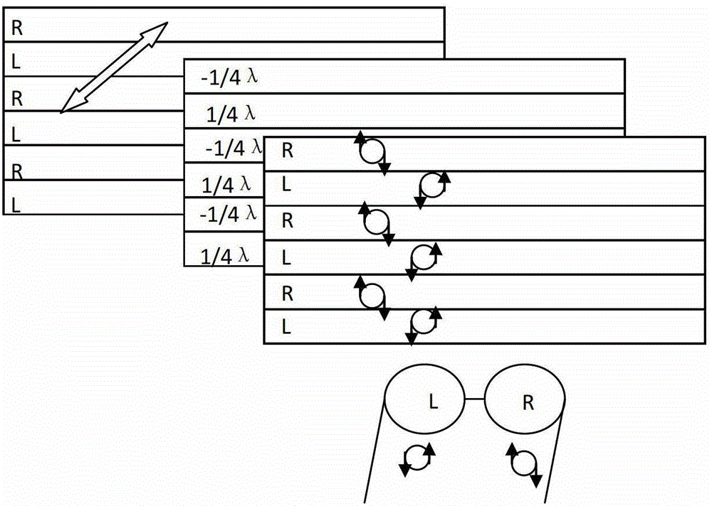
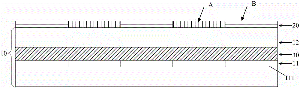
[0041] Such as image 3 As shown, a phase difference plate according to an embodiment of the present invention, the phase difference plate 20 includes a plurality of strip-shaped regions of equal width formed on the substrate, the strip-shaped regions are made of liquid crystal photo-alignment materials, and the plurality of strip-shaped regions In the region, the liquid crystal molecules in the liquid crystal photoalignment material are horizontally aligned strip regions and the liquid crystal molecules in the liquid crystal photoalignment material are vertically aligned strip regions are arranged alternately, and the horizontal orientation is parallel to the substrate , the vertical orientation is the direction perpendicular to the substrate. image 3 Among them, A is a vertically oriented strip region, and B is a horizontally oriented strip region.
[0042] Preferably, the above-mentioned substrate is a color filter substrate 10, and in the direction along the staggered ar...
Embodiment 2
[0056] This embodiment is a display device, including the phase difference plate described in Embodiment 1. The display device with the phase difference plate 20 can produce a glasses-like 3D display effect with a strong three-dimensional effect.
Embodiment 3
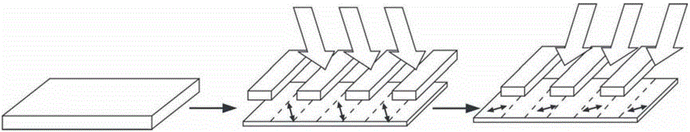
[0058] Such as Figure 6 and Figure 7 As shown, the present embodiment is the manufacturing method of the retardation plate 20 described in the first embodiment, which includes the following steps:
[0059] S1. Forming a liquid crystal photo-alignment layer on the substrate; specifically, a layer of liquid crystal photo-alignment material can be coated on the substrate by coating or spraying to prepare for the strip-shaped area formed in the next step;
[0060] S2. Exposing the liquid crystal photo-alignment layer twice to form a plurality of striped regions of equal width, so that the alignment of the liquid crystal molecules is horizontally aligned and the alignment of the liquid crystal molecules is vertically aligned. The regions are arranged in a staggered manner; wherein, the horizontal orientation is a direction parallel to the substrate, and the vertical orientation is a direction perpendicular to the substrate.
[0061] Preferably, the above-mentioned substrate is ...
PUM
 Abstract
Description
Claims
Application Information
 - R&D
- Intellectual Property
- Life Sciences
- Materials
- Tech Scout
- Unparalleled Data Quality
- Higher Quality Content
- 60% Fewer Hallucinations
Browse by: Latest US Patents, China's latest patents, Technical Efficacy Thesaurus, Application Domain, Technology Topic, Popular Technical Reports.
© 2025 PatSnap. All rights reserved.Legal|Privacy policy|Modern Slavery Act Transparency Statement|Sitemap|About US| Contact US: help@patsnap.com