
Precise forging process for front upper arm part of car chassis suspension system

A suspension system and automobile chassis technology, which is applied to vehicle parts, railway car body parts, transportation and packaging, etc. It can solve the problems of increased process, shortened service life of parts, unavoidable coarse grains, etc., and achieves enhanced mechanical properties of products , the grain size is uniform and fine, and the internal structure is evenly distributed

Active Publication Date: 2013-09-18
SHANGHAI REAL INDAL
View PDF10 Cites 28 Cited by
  • Summary
  • Abstract
  • Description
  • Claims
  • Application Information

AI Technical Summary

Problems solved by technology

[0004] For such key stress-bearing parts, if the traditional casting method is used to produce them, the blanks of the parts produced by the casting will inevitably contain casting defects such as pores, porosity, segregation, and coarse grains, which will reduce the mechanical properties of the parts and shorten the life of the parts. , and cannot meet the requirements for use under high-load conditions, and cannot give full play to the potential of the material
However, if it is processed by ordinary forging technology, the top cavity must be filled and the ribs need to be thickened, resulting in material waste, and the amount of machining in the later stage is large, the working hours are prolonged, and folding and eddy currents are prone to occur, resulting in low production efficiency and poor quality. hard to guarantee
[0005] For this type of key force-bearing parts, if the ordinary forging method is used to produce them, there is a big technical difficulty, that is, the dimensional accuracy of the thin ribs on the periphery of the parts is quite high, and the outer surface requires forging the original surface, that is, no mechanical processing after forging. At the same time, because the ribs on the periphery of the part and the lugs on the two arms are thin, the above parts are all in the deep cavity of the mold. During forging, in the deep and narrow part of the cavity, frictional resistance and vertical force caused by the mold wall In addition, the metal cooling here is faster, the deformation resistance is large, and other factors cause the plasticity of the metal in the deep cavity and thin ribs of the part to deteriorate, making it difficult to fill the lugs and ribs of the part.
It is easier to form if the cavity is filled and the outer ribs are thickened by forging. However, because there is a bolt hole at the bottom of the cavity, and the application of the suspension requires that the unsprung mass of the suspension must be small, the filled metal must be placed in the forging after forging. Milling off on the milling machine increases the process, prolongs the working hours, wastes materials, and increases the cost; and the forging flow line is cut off, the mechanical properties of the parts are reduced, and the service life of the parts is greatly shortened
Therefore, it is difficult to form such parts by ordinary forging methods.

Method used


Image

  • Precise forging process for front upper arm part of car chassis suspension system
  • Precise forging process for front upper arm part of car chassis suspension system
  • Precise forging process for front upper arm part of car chassis suspension system

Examples


Embodiment 1

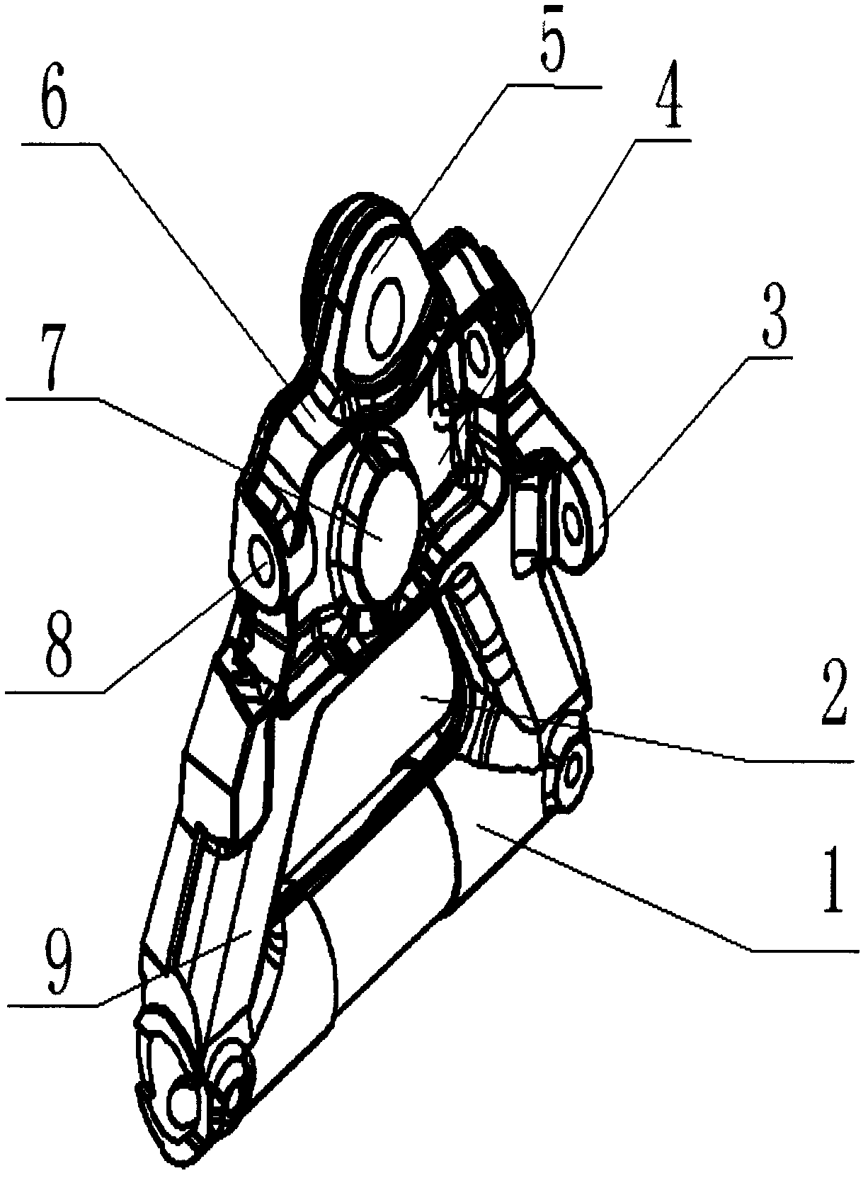
[0039] A precision forging process for parts of the front upper arm of an automobile chassis suspension system, such as figure 2 Shown: its process steps are:

[0040] Step 1: According to the part blank (such as figure 1 ) Weight, volume and process determine the blanking size (for example: choose Φ130mm bar).

[0041] Step 2: Heat the prepared bar in an intermediate frequency electric furnace at a heating temperature of 1080±10°C.

[0042] Step 3: Thicken the heated bar on the free forging hammer first, then flatten it, pull it out, and chamfer the edge; free forging is formed, before free forging, preheat the hammer head and lower anvil of the air hammer, and the preheating temperature 280°C;

[0043] The free forging hammer adopts an air hammer, the tonnage of the air hammer is greater than 750Kg, and the free forging deformation is 10% to 20%.

[0044] Step 4: Put the rough blank obtained by free forging into the die, start the friction press for the first die forgin...

Embodiment 2

[0057] The difference between this example and Example 1 is that the oxide skin should be removed during free forging, and the hammering operation method is light and heavy. The shape of the bar is broken to break the coarse carbide structure in the bar; lightly tap after finishing, the tonnage of the free forging hammer used is 1 ton, and the billet making effect is good.


PUM


Abstract

The invention relates to a precise forging process for a front upper arm part of a car chassis suspension system. The process comprises the steps of selecting a bar material, and determining the blanking size of a primary blank according to the weight and process of a forge piece; heating in a medium-frequency electrical furnace, and pre-heating an air hammer head and a hammer anvil; stacking the bar material discharged from the furnace for thickening and flattening the bar material on the air hammer, and forming into an approximate cube body by chamfering and forging; performing the first die forging molding on the freely-forged coarse blank on a friction press; cutting off a flying edge on a single-point closed type press, placing into a resistor electrical furnace for heating, performing the second die forging molding on the well-heated pre-forging blank, cutting off a flying edge on the single-point press; thermal refining; and performing shot blasting, flaw detecting and grinding. The process is capable of forming the blank of a more complex part by combining the methods of free forging and die forging, and enables a part concave cavity, a thin rib and a convex lug, which are difficultly formed, to achieve the size precision requirements; and the flow lines are distributed along the shape of the part, the internal structure is uniformly distributed, the grain size is uniform and fine, and the mechanical properties of the product are obviously enhanced in comparison with a cast product.

Description

technical field [0001] The invention relates to a front upper arm part of an automobile chassis suspension system, in particular to a precision forging process for the front upper arm part of an automobile chassis suspension system. Background technique [0002] At present, the key force-bearing parts of some high-performance automobile chassis suspension systems (such as: the front upper arm parts of the automobile chassis suspension system) have an important impact on the stability, reliability and ride comfort of the vehicle, so it is required The internal tissue performance is very high, and the streamlines are distributed along the geometric shape of the part, which can withstand working in a complex environment. [0003] see figure 1 , which is a schematic diagram of the structure of the front upper arm of the chassis suspension system of the automobile. The material of the part is 30CrA, and the weight of the part is 29Kg. As shown in the figure: the shape of the pa...

Claims


Application Information

Patent Timeline
Patent Type & Authority Applications(China)
IPC IPC(8): B21K7/12
Inventor 张钧
Owner SHANGHAI REAL INDAL
Learn More