
Blast furnace cold-intensifying and heat-avoiding type gradient brick distribution method

A gradient and heat-avoiding technology, applied in blast furnaces, blast furnace details, furnace types, etc., can solve the problems of small temperature gradient, inability to achieve longevity of the hearth and bottom of the hearth, and less cooling water, and achieve the effect of prolonging life.

Inactive Publication Date: 2013-09-18
宣化钢铁集团有限责任公司 +1
View PDF3 Cites 7 Cited by
  • Summary
  • Abstract
  • Description
  • Claims
  • Application Information

AI Technical Summary

Problems solved by technology

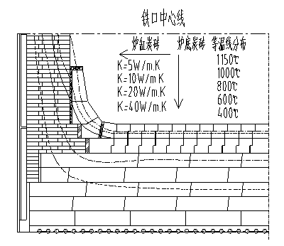
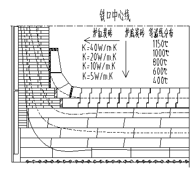
The total thermal resistance of carbon bricks in the hearth and bottom of the blast furnace is the same, but the distribution of the temperature field in the hearth or bottom of the furnace with different brick layouts is different, which affects the life of the hearth and bottom of the blast furnace. The composite hearth bottom of the "thermal method" has its own characteristics: for the hearth bottom of the "heat transfer method", the thermal conductivity of each layer of refractory material is very high, and the heat transfer is easy, but due to the high brick layer close to the molten iron Thermal conductivity, the heat of the molten iron enters the carbon bricks at the bottom of the furnace too easily, so that the ability of the cooling water to remove heat from the hearth is less than the ability of the molten iron to transfer heat to the carbon bricks, and the bottom of the hearth will continue to heat up, that is, "heat transfer Insufficient "heat avoidance" of the furnace hearth, and the temperature gradient inside the carbon brick is small, and the temperature of the carbon brick close to the cooling water is as high as 200°C, which increases the convective heat transfer between the cooling water and the carbon brick, resulting in heat at the bottom of the furnace. Too much loss, "heat transfer method" hearth bottom "heat avoidance" is insufficient, "cooling" is too large
For the hearth bottom of the "heat insulation method", the heat of molten iron is difficult to pass into it, and the temperature of molten iron cannot be lowered below the solidification line of 1150°C, that is, a "self-protecting" slag-iron shell cannot be formed, although the heat resistance of the heat insulating material is very high. High, but long-term direct exposure to high-temperature molten iron erosion, due to other thermodynamics, chemical damage and other factors, can not avoid being eroded, that is, the "heat insulation method" hearth bottom near the molten iron end "heat avoidance" is too large, due to the insulation Most of the heat is isolated by the heat insulating material. The temperature of the carbon brick layer at the bottom of the furnace is very low, especially the temperature of the carbon brick near the cooling system is low, and the heat taken away by the cooling water is very little. coefficient of carbon bricks, the cooling water is basically in the state of "useless work". The hearth bottom of the "heat insulation method" takes the loss of materials as the price of longevity, that is, the "heat avoidance" is too large, and the "cooling" is insufficient. Neither the hearth bottom of the heat transfer method nor the hearth bottom of the "heat insulation method" can achieve the longevity of the hearth bottom

Method used


Image

  • Blast furnace cold-intensifying and heat-avoiding type gradient brick distribution method
  • Blast furnace cold-intensifying and heat-avoiding type gradient brick distribution method
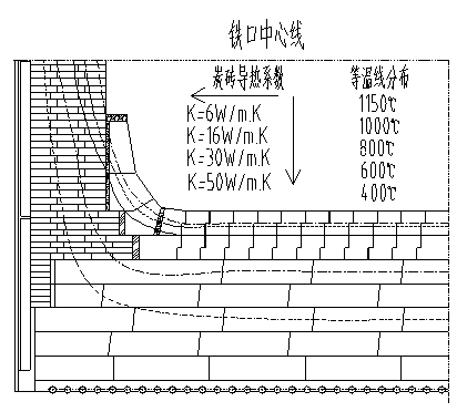
  • Blast furnace cold-intensifying and heat-avoiding type gradient brick distribution method

Examples


Embodiment 2500

[0110] Example 2500m 3 For the specific temperature field distribution of the hearth bottom of the blast furnace, see Figure 4 .

[0111] 3. The specific structure is:

[0112] (1) Bottom structure from bottom to top: leveling layer 180mm, graphite brick 400mm, semi-graphite brick 400mm, microporous carbon brick 400mm, ultra-microporous carbon brick 800mm, ceramic cup 800mm, thermal conductivity respectively 20, 70, 20, 16, 20, 4.5 W / mK, the thermal conductivity of the refractory material gradually increases from near the hot surface of the molten iron to the cooling system, forming a gradient, which basically conforms to the gradient brick layout method of the present invention for raising cold and avoiding heat. The specific analysis is as follows:

[0113] Leveling layer: The traditional leveling layer adopts carbon ramming material, which has the problems of low actual thermal conductivity, unreliable ramming, and long construction time. The actual thermal conductivity...


PUM


Abstract

The invention relates to a blast furnace cold-intensifying and heat-avoiding type gradient brick distribution method and belongs to the technical field of long life of iron-making blast furnaces. According to the technical scheme, the method comprises the following process steps of: (1) performing flat steel mesh installation and leveling layer construction on the blast furnace hearth and furnace bottom, and sequentially performing layered construction; (2) performing wall-to-wall furnace bottom graphite brick masonry construction on the layer I; (3) performing wall-to-wall furnace bottom carbon brick masonry construction on the layers II, III, IV and V; (4) performing furnace bottom ceramic cup pack-up block masonry construction; (5) performing furnace bottom and hearth side wall carbon brick masonry construction; and (6) performing hearth ceramic cup wall masonry construction. Because the brick layers of different heat conductivity coefficients are arranged at the hearth and the furnace bottom, the heat conductivity coefficient of each refractory material layer is gradually increased from the surface close to a molten iron heat surface to a cooling surface so as to form gradient. The method has the advantages and effects that the heat conductivity coefficient and an arrangement mode of the refractory material used by the hearth and the furnace bottom are changed, so that an optimal cooling or thermal insulating effect is achieved, and the service life of the hearth and the furnace bottom is prolonged.

Description

technical field [0001] The invention relates to a gradient brick laying method of blast furnace cooling and heat avoidance type, and belongs to the technical field of longevity of ironmaking blast furnaces. Background technique [0002] Realizing the longevity of the blast furnace is an effective way to reduce the cost of blast furnace ironmaking. The hearth and bottom erosion are the main factors affecting the high efficiency and longevity of the blast furnace, and the life of the hearth and bottom determines the life of the blast furnace. In comparison, the longevity of blast furnaces in my country There is still a gap between the level and the foreign advanced level, and only a few blast furnaces can achieve the longevity goal of 10 to 15 years. The total thermal resistance of carbon bricks in the hearth and bottom of the blast furnace is the same, but the distribution of the temperature field in the hearth or bottom of the furnace with different brick layouts is different...

Claims


Application Information

Patent Timeline
IPC IPC(8): C21B7/02C21B7/06
Inventor 魏小珍郭喜斌郑艾军李豪杰程树森赵存军王涛庞江岑亚虎
Owner 宣化钢铁集团有限责任公司
Learn More