
Temperature control system-based evaporation temperature control method for OLED (Organic Light Emitting Diode) organic layer

A technology of temperature control system and temperature control method, applied in vacuum evaporation plating, coating, sputtering plating and other directions, can solve the problems of easy decomposition, long time stability of evaporation temperature and deposition rate, material degeneration, etc. The effect of avoiding degradation and denaturation, shortening stabilization time, and reducing production costs

Inactive Publication Date: 2013-09-18
SICHUAN CCO DISPLAY TECH
View PDF5 Cites 25 Cited by
  • Summary
  • Abstract
  • Description
  • Claims
  • Application Information

AI Technical Summary

Problems solved by technology

Nevertheless, the temperature control of OLED organic layer evaporation process still has the following problems: (1) organic materials are easy to decompose and denature at high temperature, and excessive temperature fluctuations in the heating sublimation process will lead to the danger of material denaturation; (2) evaporation temperature and deposition Too long rate stabilization time leads to low utilization of expensive organic materials and increased production costs; (3) The temperature accuracy is not controlled well, and the deposition rate is unstable, resulting in poor film uniformity and low doping ratio of guest materials are difficult to control, Affect device light emission

Method used


Image

  • Temperature control system-based evaporation temperature control method for OLED (Organic Light Emitting Diode) organic layer
  • Temperature control system-based evaporation temperature control method for OLED (Organic Light Emitting Diode) organic layer
  • Temperature control system-based evaporation temperature control method for OLED (Organic Light Emitting Diode) organic layer

Examples


Embodiment Construction

[0029] In order to make the object, technical solution and advantages of the present invention clearer, the present invention will be further described in detail below in conjunction with the accompanying drawings and embodiments. It should be understood that the specific embodiments described here are only used to explain the present invention, not to limit the present invention.

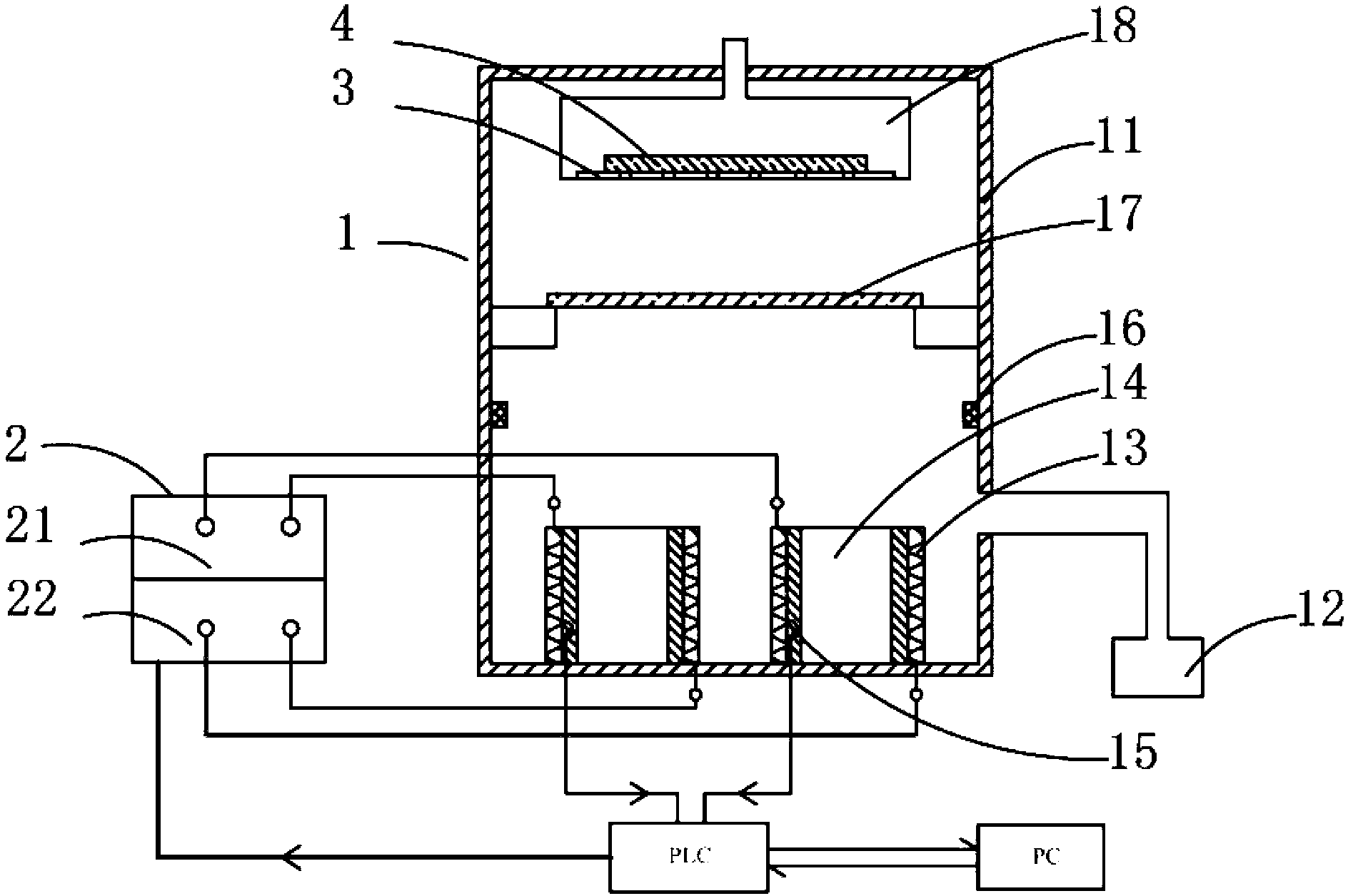
[0030] The temperature control system used in this embodiment, figure 1 As shown, it includes vacuum evaporation device 1, external control power supply 2 and control system. A resistance wire heating source 13 surrounds the two evaporation sources 14 and controls each evaporation source 14 individually; a thermocouple 15 is located between the evaporation source 14 and the heating source 13 for monitoring the temperature of each evaporation source 14 The rate sensor 16 is arranged on the wall of the vacuum chamber 11 on the top of the evaporation source 14 for monitoring and recording the deposit...


PUM


Abstract

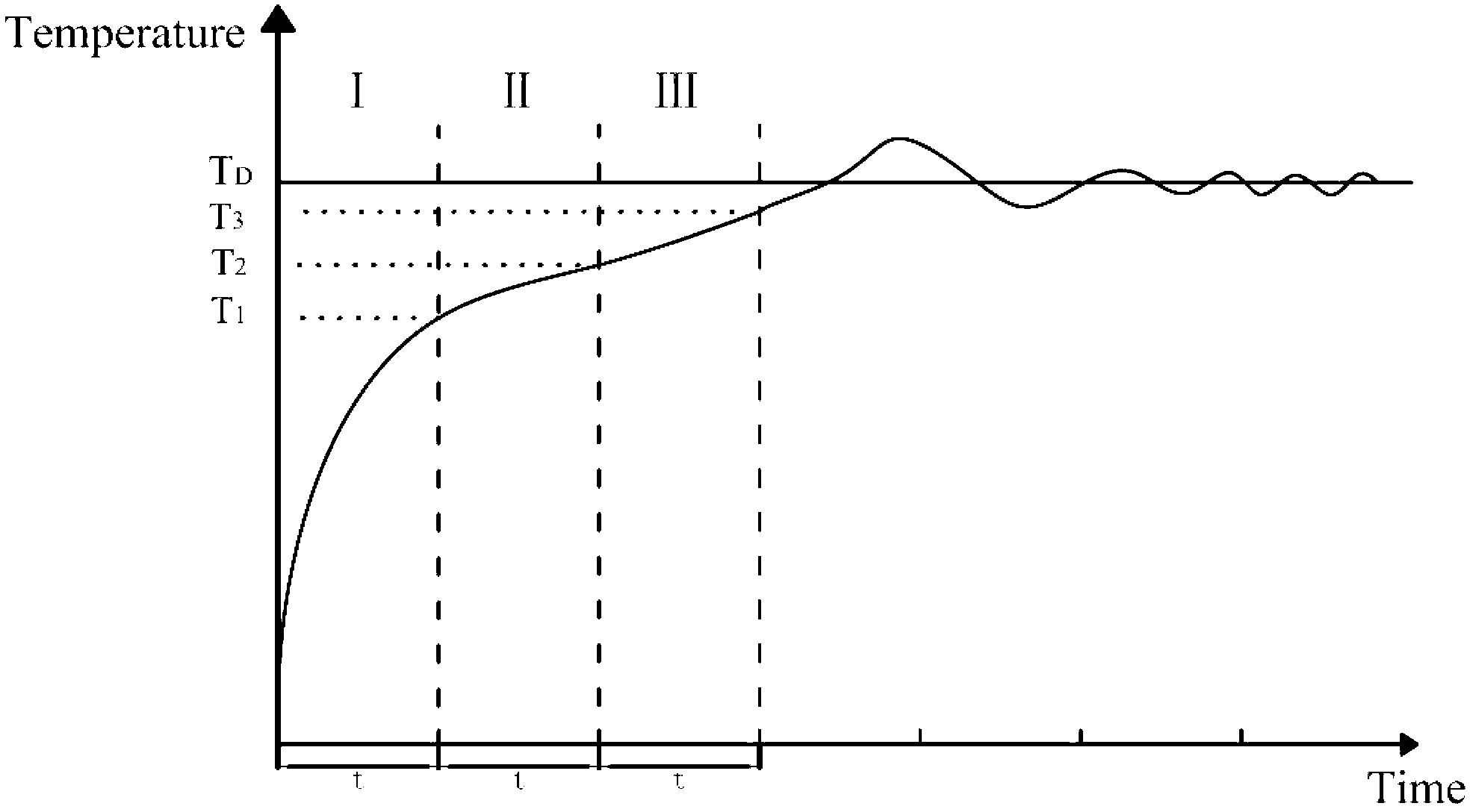
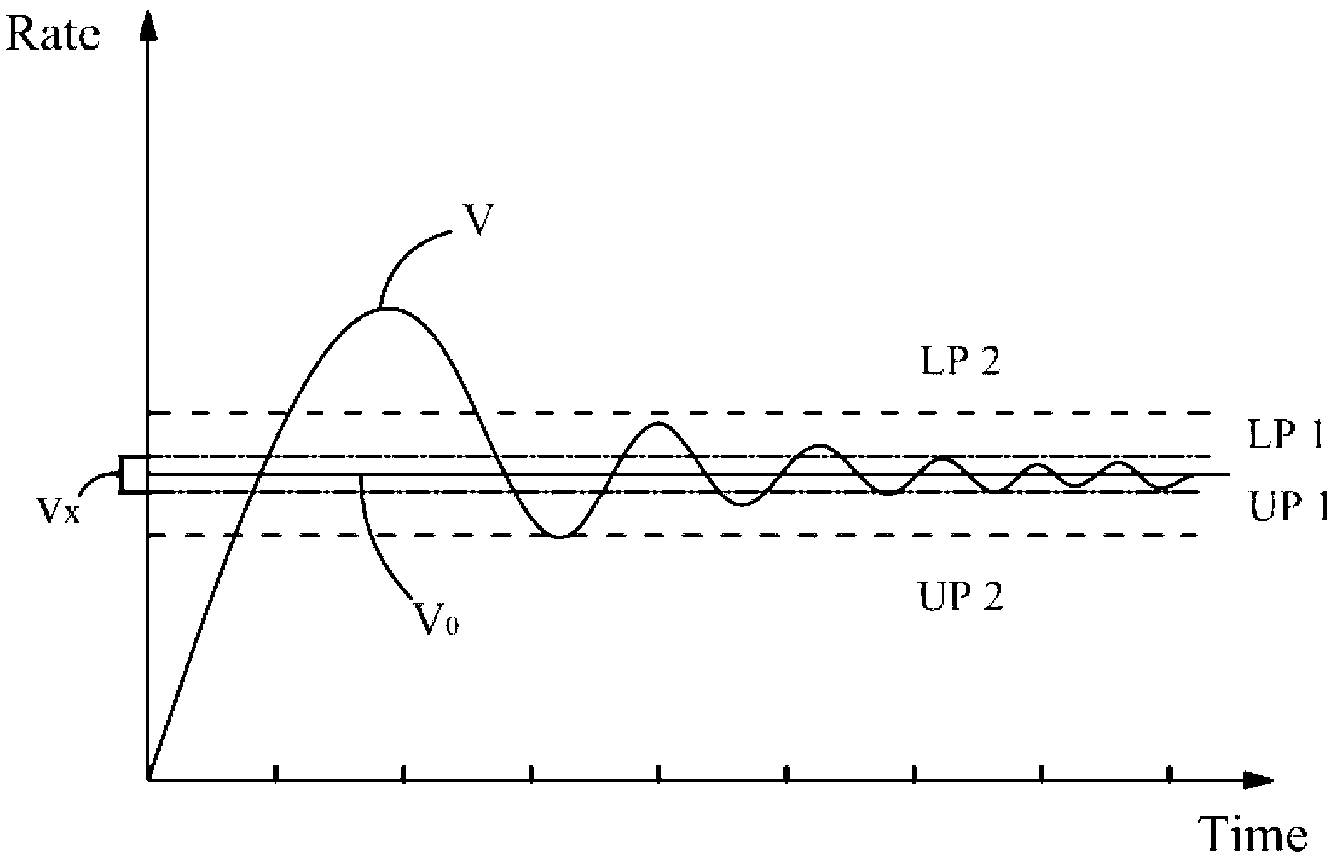
The invention discloses a temperature control system-based evaporation temperature control method for an OLED (Organic Light Emitting Diode) organic layer. The evaporation temperature control method comprises a preheating process and an evaporation process, wherein the preheating process is divided into three temperature-rise processes with temperature gradients; the evaporation process comprises a step of controlling the temperature of an evaporation source by controlling the power of an evaporation power supply on the basis of an actually-measured deposition rate curve. According to the temperature control system-based evaporation temperature control method for the OLED organic layer, the stabilization time of the temperature of the evaporation source and the deposition rate is shortened, the use ratios of the organic materials of the evaporation source are improved, meanwhile, the degradation, the degeneration and the like of the organic materials caused when the temperature rise is too fast or the risen temperature is too high are avoided, and the production cost is lowered; by utilizing a characteristic that the evaporation rate is changed by 20-30% when the evaporation temperature is changed by 1%, the accuracy of the temperature control is improved, the stability of evaporation temperature is maintained, and the uniformity of evaporated films is improved.

Description

technical field [0001] The invention belongs to the technical field of organic electroluminescence display, and in particular relates to a method for controlling the evaporation temperature of an OLED organic layer based on a temperature control system. Background technique [0002] The OLED display device forms the carrier transport layer and the organic light emitting layer in the device by evaporating an organic light emitting material into a film. The preparation method of organic thin film layer, known has vacuum vapor deposition method, is divided into three basic processes: the deposition process of heating evaporation process, transportation process and substrate surface, wherein the main factor of heating evaporation stage is the material Saturation vapor pressure, saturated vapor pressure is related to temperature, it increases as temperature rises and decreases as temperature falls. According to the kinetic theory of gas molecules, the rate of change of depositio...

Claims


Application Information

Patent Timeline
IPC IPC(8): C23C14/54C23C14/12C23C14/24H01L51/56
Inventor 李莉莉赵芳吴锐魏锋任海
Owner SICHUAN CCO DISPLAY TECH
Learn More