Method for eliminating periodic non-linear error or interference in signal transmission process

A nonlinear error and signal transmission technology, applied in the field of signal transmission, can solve problems such as inaccurate results, large amount of calculation, and poor real-time performance

Inactive Publication Date: 2013-09-25
CHANGCHUN INST OF OPTICS FINE MECHANICS & PHYSICS CHINESE ACAD OF SCI
View PDF5 Cites 3 Cited by
  • Summary
  • Abstract
  • Description
  • Claims
  • Application Information

AI Technical Summary

Problems solved by technology

[0005] In order to solve the technical problems of the existing signal transmission system (including laser heterodyne interferometry system) such as complex system, large amount of computation, poor real-time performance, and inaccurate results, the present invention provides a periodic nonlinear error or The interference elimination method can eliminate the nonlinear error or the specific harmonic componen

Method used


Image

  • Method for eliminating periodic non-linear error or interference in signal transmission process
  • Method for eliminating periodic non-linear error or interference in signal transmission process
  • Method for eliminating periodic non-linear error or interference in signal transmission process

Examples


Embodiment 1

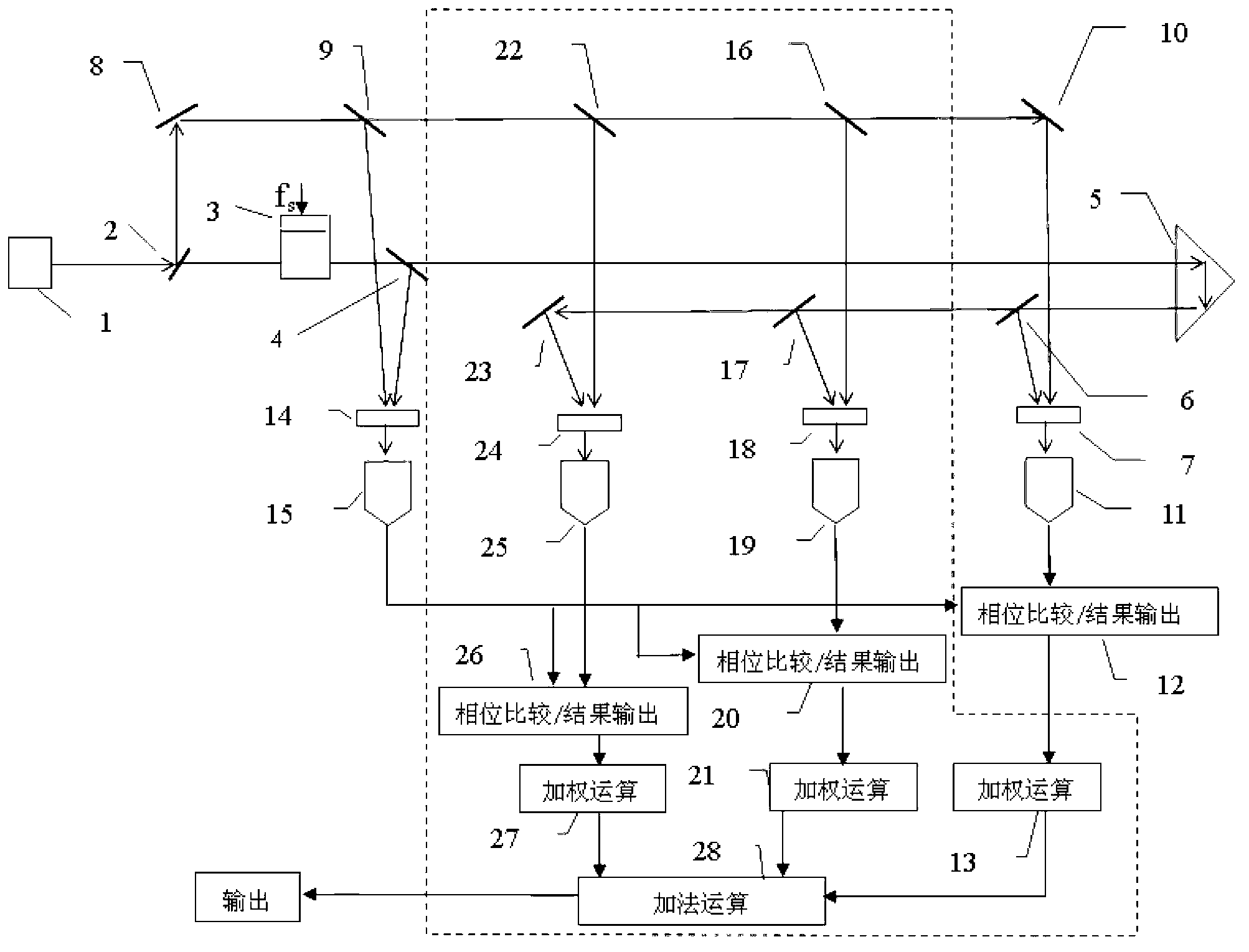
[0066] The basic implementation of the nonlinear error elimination method in the laser heterodyne interferometry that can avoid the corresponding precise optical adjustment is as follows: figure 1 shown. On the basis of an original laser heterodyne interferometer, the present invention adds the part in the dotted line box in the figure to cooperate with the whole to complete the structure, principle and function described in the present invention.

[0067] First of all, we explain the working principle of the original heterodyne interferometry system. The laser is emitted by the laser 1, and enters the acousto-optic device 3 through the partial reflector 2. After being frequency-shifted, it exits to the partial reflector 4. The transmitted light is transmitted by the measuring prism 5. Reflected back, it is incident on the partial reflector 6, and the reflected part interferes with another beam of light passing through the polarizer 7. The light reflected by the partial refl...

Embodiment 2

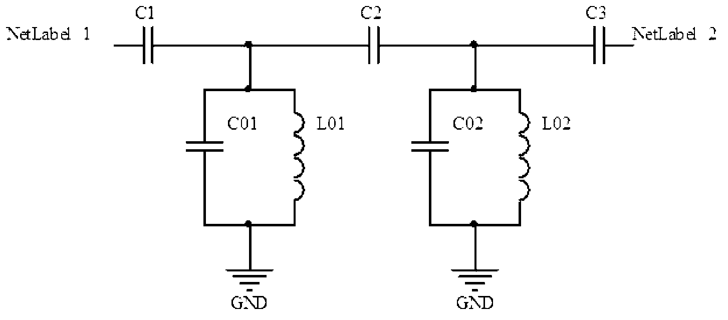
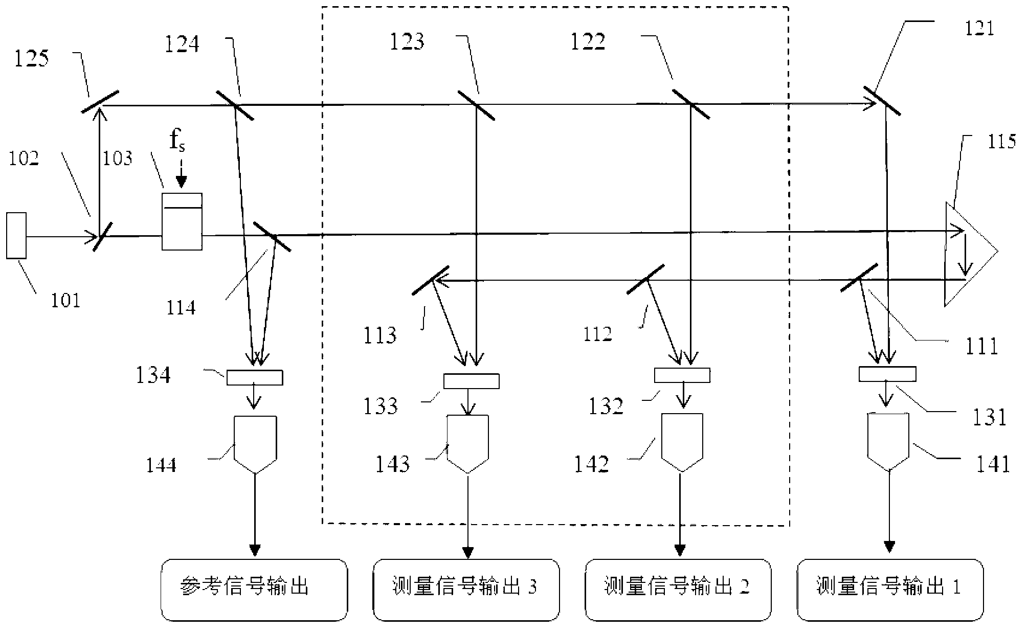
[0075] In this embodiment, the photoelectric signal is filtered by a filter composed of two or more stages of resonant circuits, and the phase difference between each measurement signal and the reference signal is calculated by the square wave duty ratio average method. The entire laser heterodyne interferometry system can be divided into the optical part and the subsequent electronic signal processing part. The principle of the optical part is as follows image 3 As shown, on the basis of an original optical part, the present invention adds the part in the dotted line box in the figure.

[0076] First, the working principle of the optical part of the original heterodyne interferometry system is described: the laser light is emitted by the laser 101, and enters the acousto-optic device 103 through the first part of the mirror 102, and is frequency-shifted and then emitted to the second part of the mirror 114, and the transmitted light It is reflected back by the measuring pri...


PUM


Abstract

The invention discloses a method for eliminating a periodic non-linear error or interference in a signal transmission process, and belongs to the field of signal transmission. According to the method, on signal paths with periodic non-linear errors or interference elements, at least signals on three paths are obtained and phase angles of signal frequency elements to be eliminated, of the periodic non-linear errors or the interference elements on the paths are made to be different in one corresponding circumferential angle range or a corresponding circumferential angle range after integer multiples of circumferential angles are eliminated, and the periodic non-linear errors or the interference elements are eliminated or restrained through a subsequent electronic processing method. The method is capable of eliminating specific harmonic wave elements of the non-linear errors or the interference, the adjustment process is very easy, the performance of a system is improved, and cost is lowered.

Description

technical field [0001] The invention belongs to the field of signal transmission, in particular to a periodic nonlinear error or interference elimination method in the signal transmission process, which can be applied to the field of laser heterodyne interferometry (Heterodyne Interferometry) measurement in optical precision measurement technology. Background technique [0002] Take the laser heterodyne interferometry system as an example, which can be used to measure physical quantities such as displacement and length, and is one of the best nanometer measurement methods. This method is to convert the measured displacement into the frequency or phase change of the heterodyne signal, and then measure this change. Since the frequency of the heterodyne signal is much lower than the optical frequency, the photoelectric signal is easy to process and can be processed electronically. Points to achieve higher measurement resolution, the resolution can reach picometer (pm) or better...

Claims


Application Information

Patent Timeline
IPC IPC(8): G01B11/02G01D3/032
Inventor 李也凡
Owner CHANGCHUN INST OF OPTICS FINE MECHANICS & PHYSICS CHINESE ACAD OF SCI
Why Eureka
Try Eureka